Wiring harness design in CATIA V5 - 3D modeling Week 2 Challenge
1.
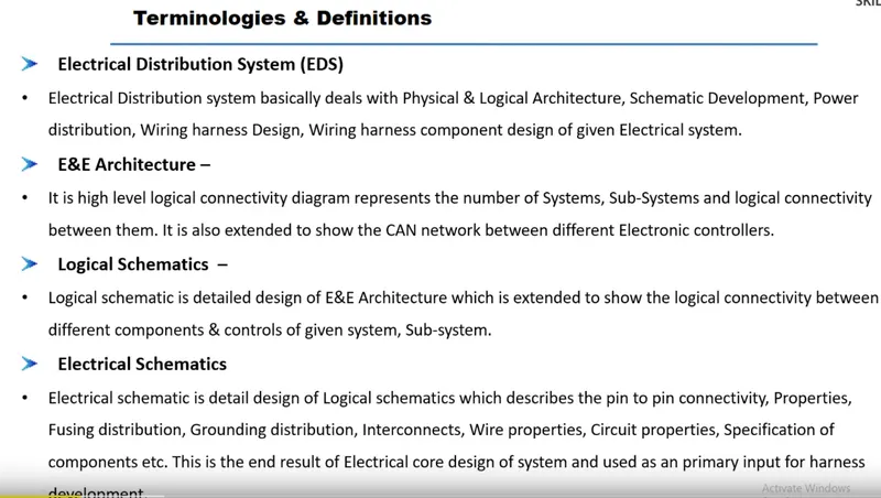
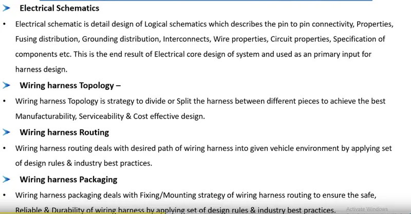
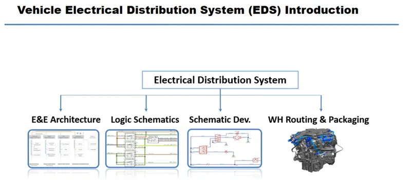
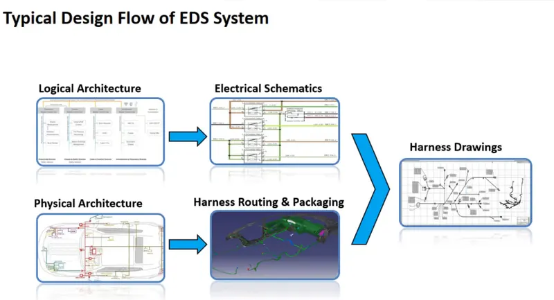
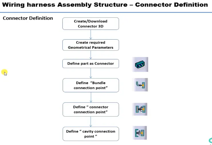
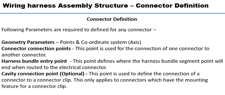
1. Connector Definition:
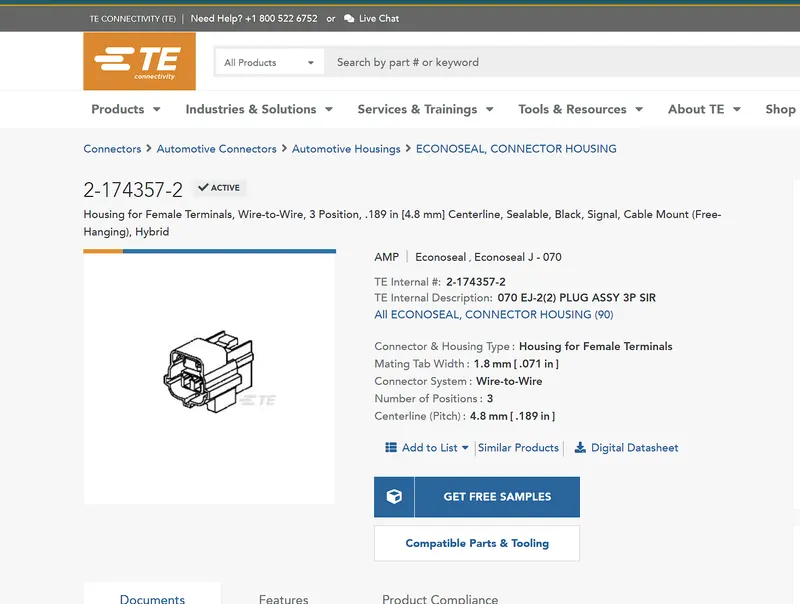
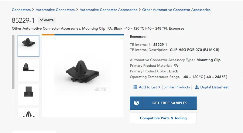
As shown in flowchart, first download the connector CAD either IGS or STP of DT06-08SA, Tyco 174357-2, Tyco 85229-1 from te.com are worked in the CATIA V5 Software.
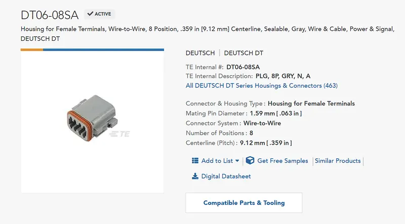
1. DT06-08SA:
After downloading the CAD file, then define the geometrical parameters.
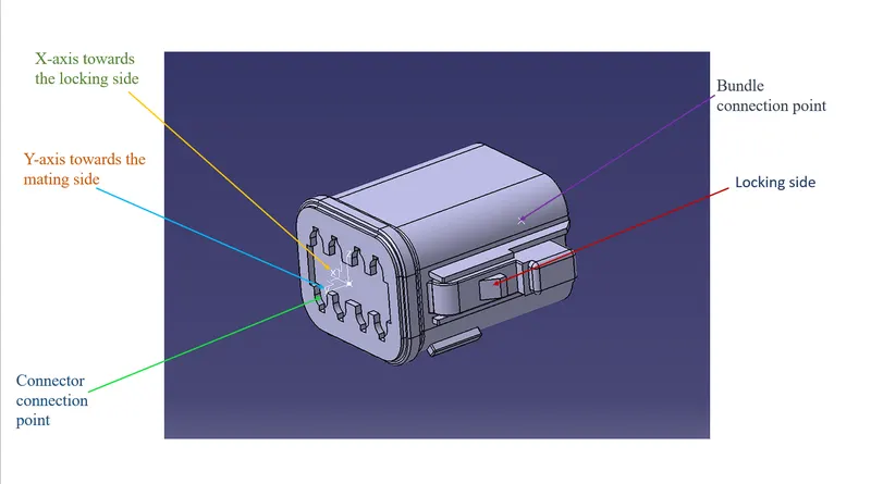
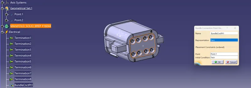
As shown in the fig. create the points at the Bundle entry and Connector mating surfaces, then create the axis system such that y-axis pointed in the direction of mating of connector, x-axis pointed towards the locking mechanism of the clip and z-axis towards the connector left to right.
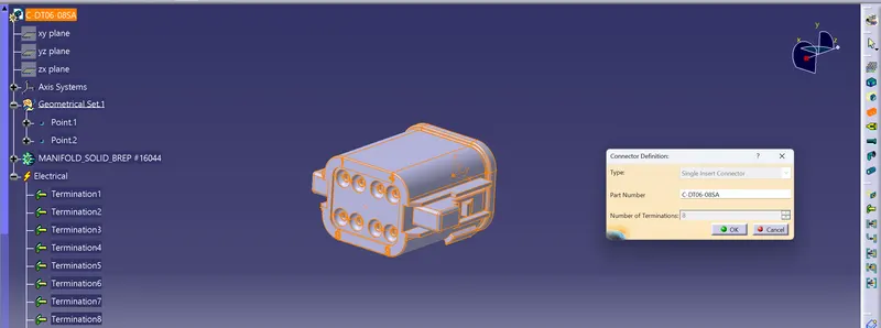
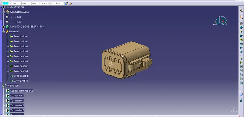
Then the CAD part is defined as Connector(part is converted into mechanical to electrical part) in the Electrical part Design workbench
- Bunddle connection point definition
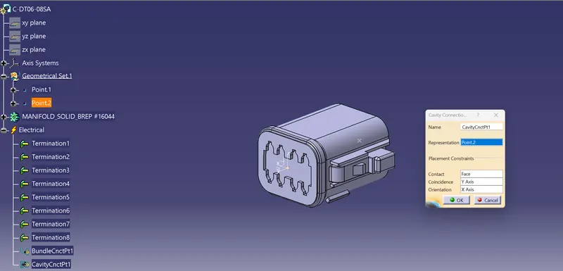
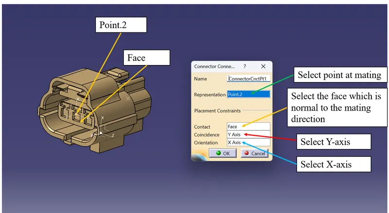
- Connector connection point definition
- Finally the part is defined as Connector
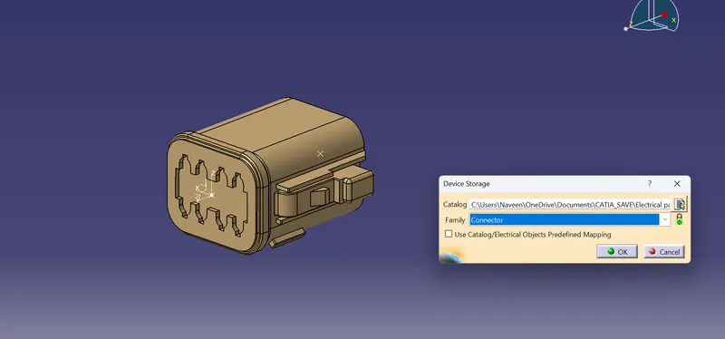
- Store the part in the catalogue by clicking the storage tool
- Here the cavity connection point is not required because it as no cavity for the mounting clip.
2. Tyco 174357-2
After downloading the CAD file, then define the geometrical parameters.
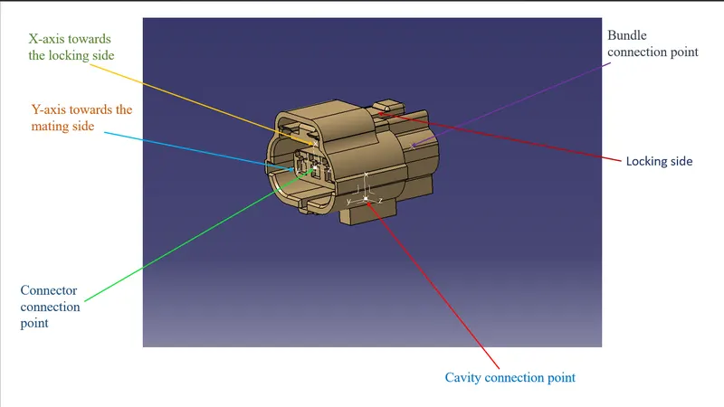
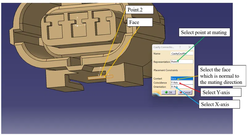
Here the cavity connection point and axis is created as same as the connector connetion point directions.
- Define it as Connector- Add number terminations as 3 because it has 3 bundle entry as show in the fig.
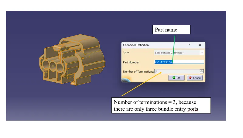
- Bunddle connection point definition
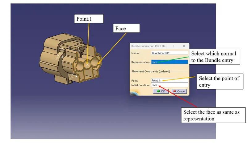
- Connector connection point definition
- Cavity connection point definition
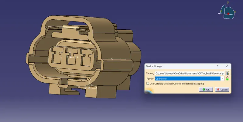
Save it in the catalogue by using the storage tool.
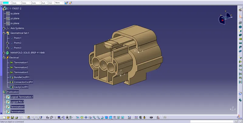
3. Tyco 85229-1
After downloading the CAD file, then define the geometrical parameters. Here the whole mounting clip is defined as Cavity.
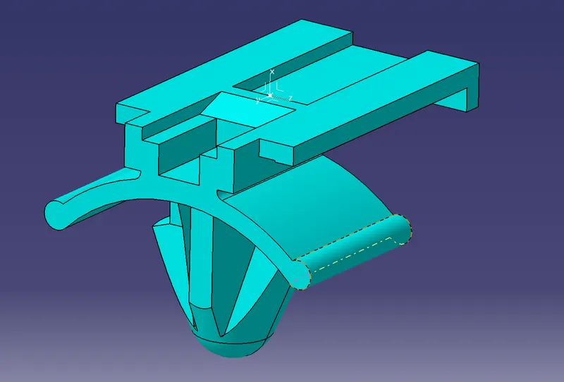
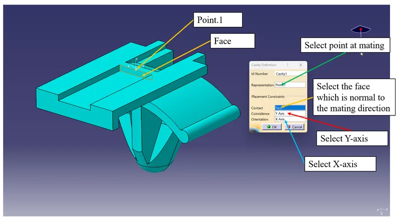
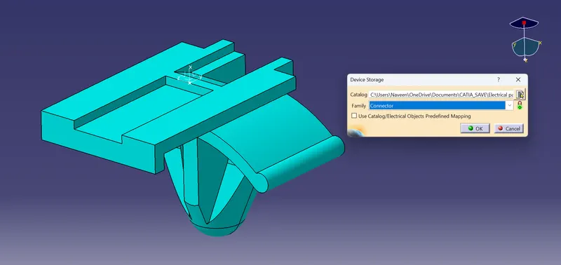
Save the model in tthe catalogue
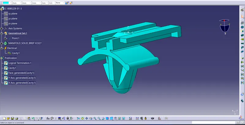
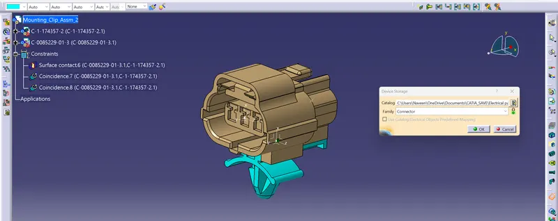
After the defining all the neccessary Electrical propertise to the both model shown in above, now it has to be form a cavity connection b/w the models by Electrical Assembly Design workbench. Using Connect Electrical devices tool connect both mounting clip and female connector.
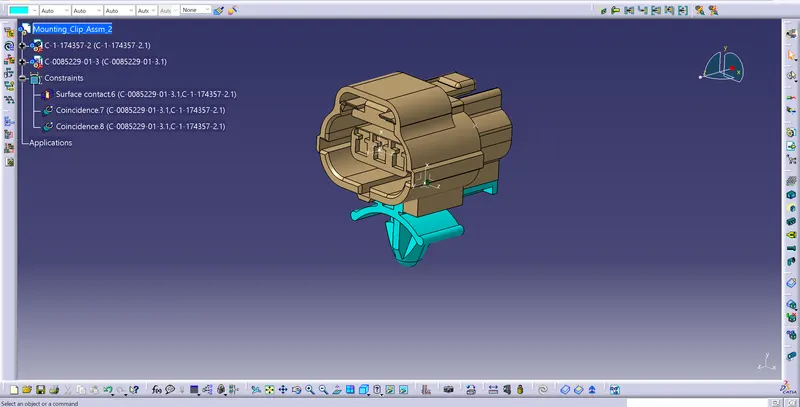
Save the model in the catalogue by storage option.
Conclusion: The connectors are defined as per the flow chart as shown in the above fig. and saved in the catalogue for attachment purpose (We can avoid to define the connector as electric again and again).