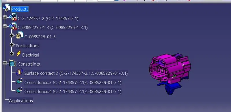
Wiring harness design in CATIA V5 - 3D modeling Week 2 Challenge
- sign part. shown in above fig.
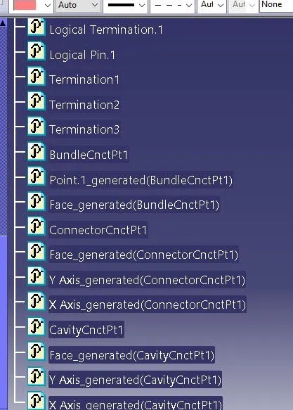
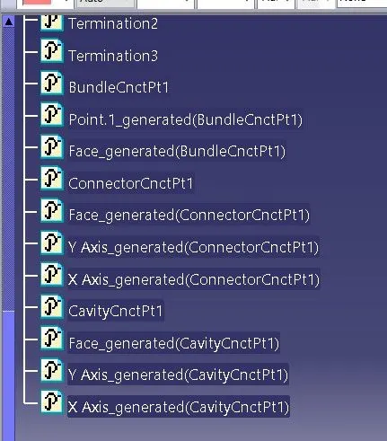
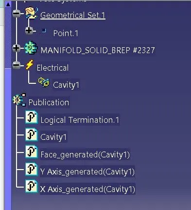
- In contact select the face on which point is created and for coincidence and orientation y-axis and x-axis respectively.
- Then select ok. So, it is ready for assembly for mounting of clip.
Procedure for mounting clip
- Download the part by given link.
- Go to mechanical design and then part design.
- The mounting part have to select for the point and axis.
- Now Select point definition tool select the between option and then select the two points with midpoint. The point will be formed as follow.
- In red colour it is defined the two points.
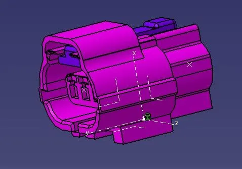
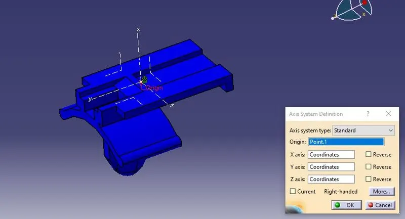
- After this the axis system definition system is use to give axis. As shown in following figure.
- The x-axis is towards the mounting and y-axis towards surface.
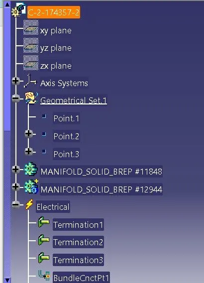
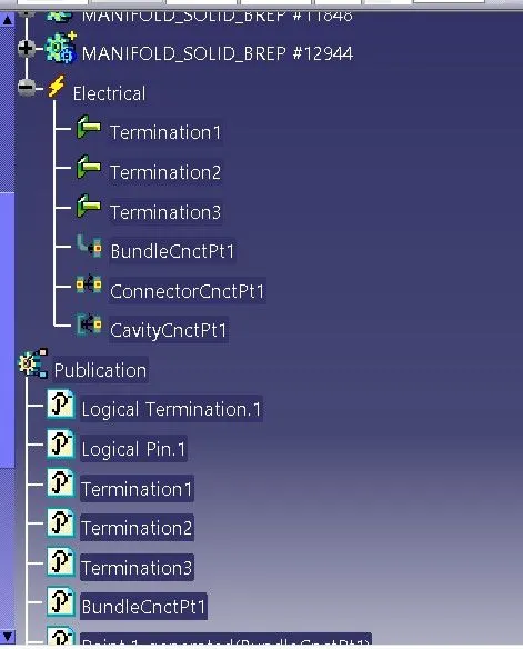
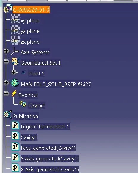
- Now we have to defined it as a cavity. Then go to electrical part design.
- after that first it has to defined as equipment.
- For that Go to define equipment tool select it then select the mounting clip then select ok.
- Now go to caity definition tool and select the mounting
- For that go to the electrical part design and select tool cavity definition.
- In that representation will be the point we have created. The contact, coincidence and orientation will be face, y-axis and x-axis respectively.
- Then select ok. Now it is defined electrically.
Assembly of connector and mounting clip
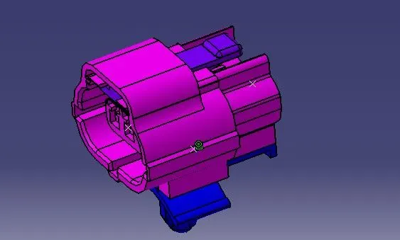
- Copy the connector and mounting clip and paste it in electrical assembly design.
- By using the command assembly design in mechanical design separate the two parts and arrange in proper way.
- Then go to electric assembly design in that use tool connect electrical devices.
- By clicking on connect electrical devices then connect the two parts.
- By doing this electrical assembly is done.
- The red colour denoting the connect electrical devices tool.