Wiring harness design in CATIA V5 - 3D modeling Week 2 Challenge
Defining Connector 1
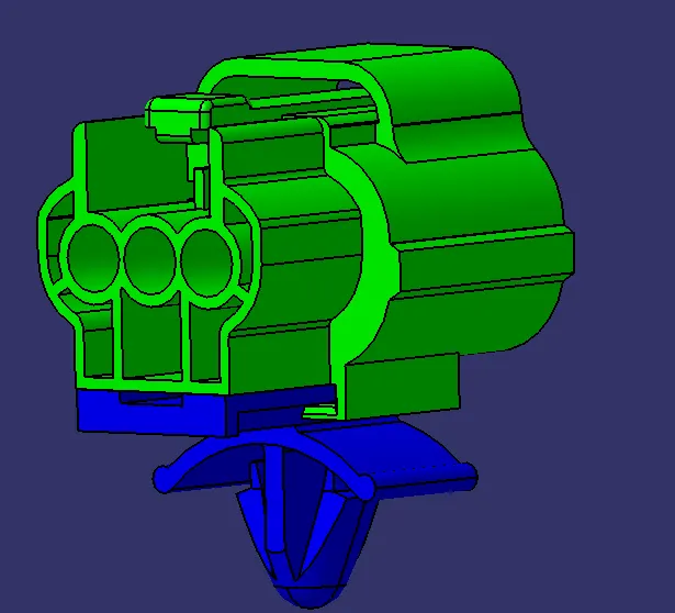
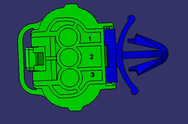
The given connector is Being Defined in Electrical Part Design Workbench. The details are listed below:
3 points and 2 axis systems are being created, 1 for connector connection provision. 2for bundle entry provision. 3 for Mounting clip provision,
- Firstly, the connector connection point is defined, it is done as below
- Created a midpoint on contact face which will be normal to wire bundle inertion.
- Created an connector connection axis system at this point, with the direction of XYZ axis as shown in below.
- Created Cavity connection point
- Created Cavity connection axis system
- Created point for bundle entry
- There was no hard and fast as such rules to give directions of XYZ but it is to be ensured that this directions are followed in the exact manner while definining its mate also.
- Finally, Define Connector connection point and cavity connection point.
Defining Connector 2
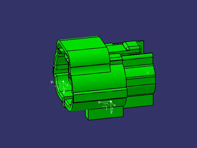
The given connector is Being Defined in Electrical Part Design Workbench as similar to the above except that this connector was lacking with cavity connection,
Hence 2 Points and 1 axis system is created, 1 for connector and 2. for bundle entry
The details are listed below:
- Firstly, the connector connection point is defined,
- Created a midpoint on contact face which will be normal to wire bundle inertion.
- Created an connector connection axis system at this point, with the direction of XYZ axis as shown in below.
- Created Bundle entry point
- Created Bundle entry axis system
- There was no hard and fast as such rules to give directions of XYZ but it is to be ensured that this directions are followed in the exact manner while definining its mate also.
- In Electrical part design, define the part as connector, gave the number of terminations as 8 as we had 8 entry points of wire.
- Finally, Define Connector connection point and cavity connection point.
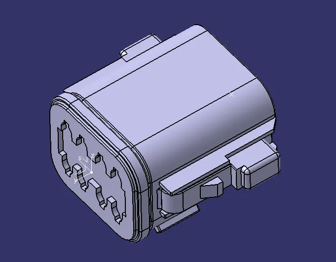
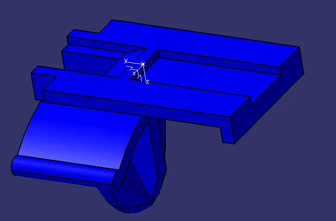
Defining mounting clip
Created a midpoint on the curve/ line that meets the connector,
created an axis system following to directions as same as C-1
Assembling C1 and Mounting clip,
Both the parts are copied to Electrical assembly design workbench and they are being mated using Connect electrical devices tool.