Week 9 - Project - Master Section Development
DESIGN AND DEVELOPMENT OF B-PILLAR INTERIOR
AIM -
The main aim of this challenge is to develop B –pillar section using Class A surface and intersection for Dog House given following Design Rules create Ribs And perform draft analysis for the plastic component created.
DIRECTION OF TOOLING AXIS – The direction in which the mold and Cavity opens in the tooling Axis.
CREATION OF TOOLING AXIS -
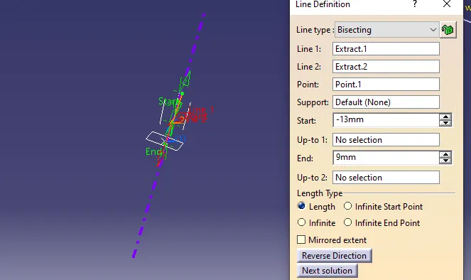
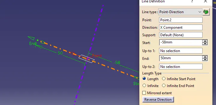
Using the given master sections bisecting lines created and normal to class A surface will be created and treating as Tooling Axis.
FLANGES CREATION –
Visualizing the master section, we can clearly understand that A surface will be having flanges and the final component should be created with flanges.
The flanges were created by creating a sweep from the boundary created from the Class –A Surface using reference curve option.
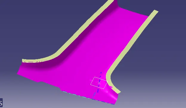
The flange will be trimmed with Class –A and fillet will be given according to the fillets on master section and this will be the surface used for creation of class –B & C Surface.
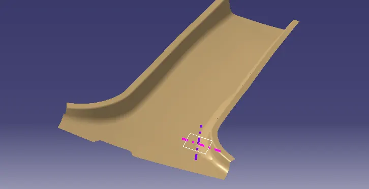
CLASS –B CREATION
As the most surface is flat and don’t have many bends and simple, we can directly offset the class-A surface to the thickness of the component.
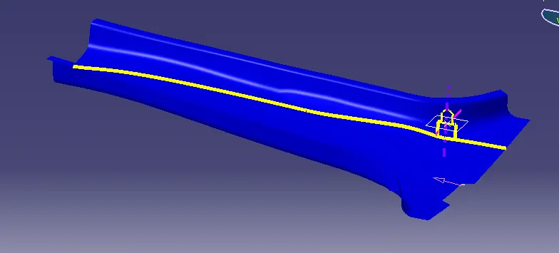
CLASS –C CREATION
Class-C surface created using the class –A surface by creating multiple extract of the boundary of Class –A and the surface is swept with the draft.
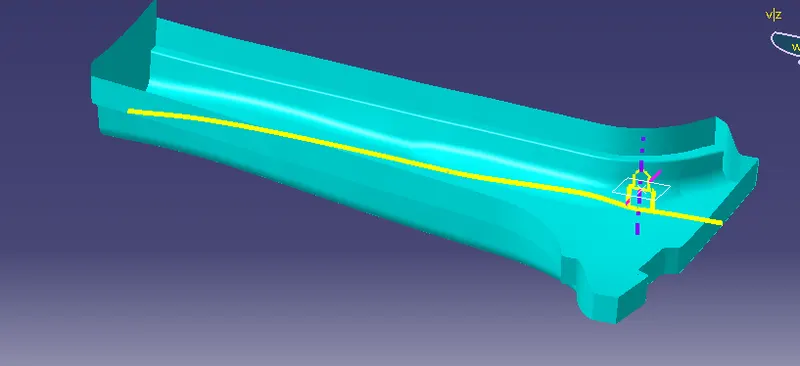
The class –C will be trimmed with the class –A and the final trim will be trimmed with Class –B to form a complete closed surface.
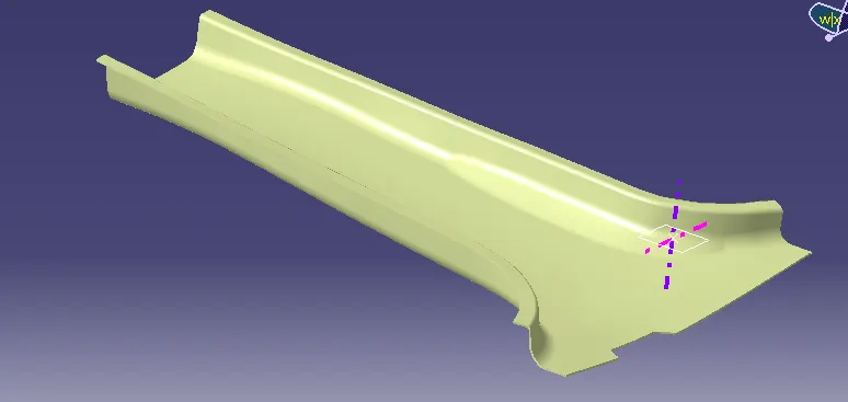
The closed surface will be converted in to a solid body using Close surface in part workbench.
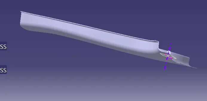
DRAFT ANALYSIS FOR CLASS –A
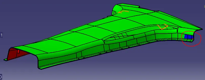
Here we can see surface is satisfying the draft except at a small particular location which is showing in blue Colour.
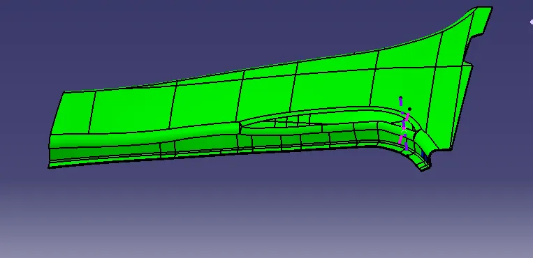
SIDE CORE LIFTER TOOLING AXIS-
A tooling axis should be created for the dog house to clear the draft analysis as an undercut will be formed if we use the main tooling axis so a side core axis will be created.
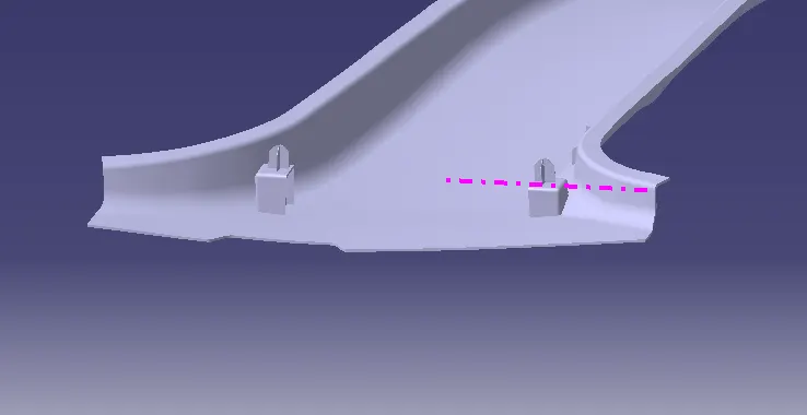
DOG HOUSE CREATION
Using the master section, we can created the profile for dog house.
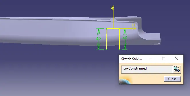
The profile is surface extruded along the side core tooling axis with the required draft produced in the sketch itself and a profile for avoiding shrinkage will also be created. The main use of the dog house is to provide support and to avoid sink marks.
The surface is thickened to the thickness of the component and the body is split for the profile to avoid shrinkage.
Draft is provided for the inner walls, and fillets will be provided to both inner and outer surface.
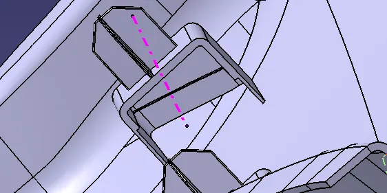
4-WAY LOCATOR CREATION –
The 4 –way locators are also located and created using the master sections.
The profile is padded along the tooling axis direction and chamfer and fillets are provided.
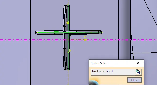
As there are two dog house profiles in the master sections another dog house will be created using the symmetry.
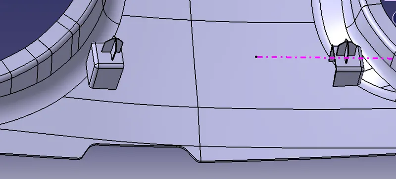
Checking with master sections-
As we can see that the dog house created should match with the master section given, but here in this model an extra profile added to avoid marks following the design rules.
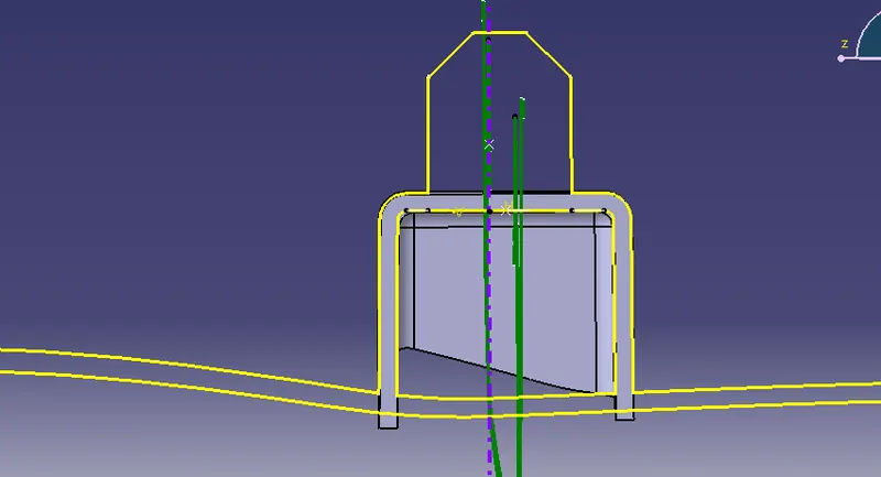
DRAFT ANALYSIS FOR DOG HOUSE –
By seeing the below images we can say that dog house has meet the required draft
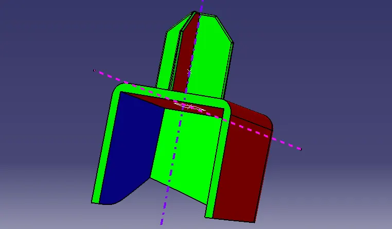
RIBS CREATION –
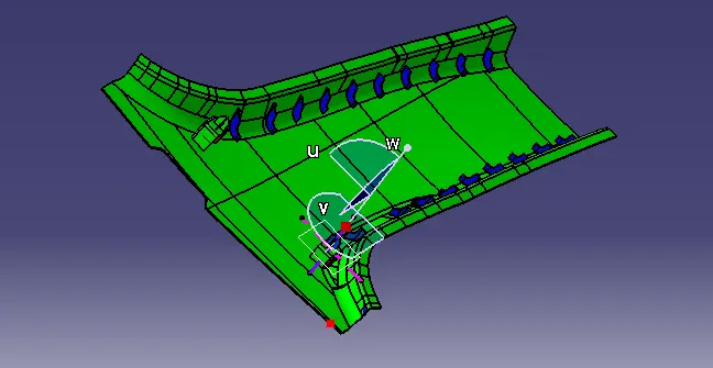
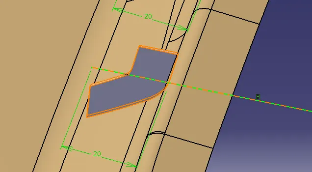
The ribs should be created at a 50mm distance apart from each other and the design rules should be followed.
The ribs are split according to the design rules.
The final component with all feature is-
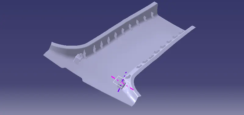
DRAFT ANALYSIS FOR B- PILLAR –
By seeing the below images, we can say that component has met the required draft except at a particular small portion with blue and red.