Week 9 - Project - Master Section Development
AIM
To Create the B-pillar solid from the class A surface in CATIA V5
SOFTWARE USED
CATIA V5
OBJECTIVES
- Create a sketch by using Positioned sketch
- All the should be sketches should be Iso-Constrained
- Ensured Proper Tree Structure
- Geometrical sets should having a proper name based on the sketches present inside of it
- All the required sketches for the Solid Feature should be created under the Geometrical set and the Part body should only have the Solid Features.
PROCEDURE
STEP 1
Create a tooling axis by the reference of master section by using bisecting method
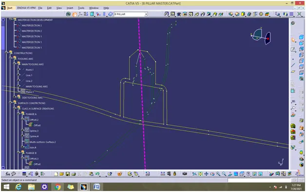
STEP 2
Offset the class A surface for the thickness of 2mm to create a class B surface
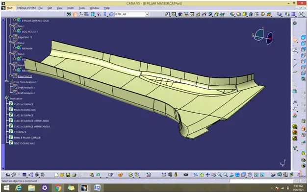
STEP 3
Create a flange on both the surfaces by the reference of master section by using sweep command on the direction of main tooling axis
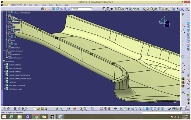
STEP 4
Create a class C surface by sweeping all the boundaries of class b surface separately for the angle of 3 degree
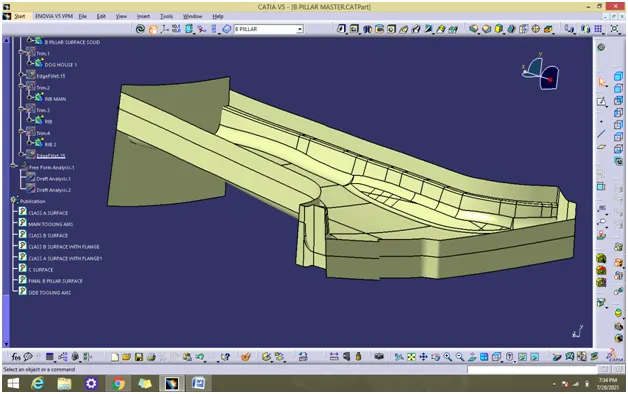
STEP 5
Trim the c surface with class b and class a surface
Use close body command to make solid part.
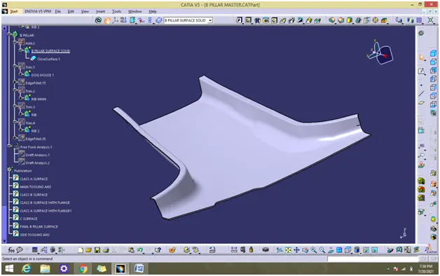
STEP 6
Create a dog house and 4 way locator by the reference of master section.
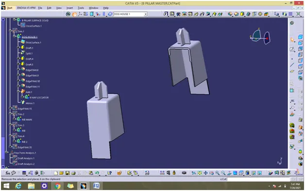
Step 7
Create a rib for 50mm around the surfaces by following the design rules
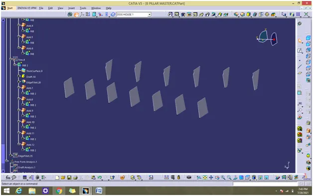
SKETCHES USED IN B PILLAR
DOG HOUSE
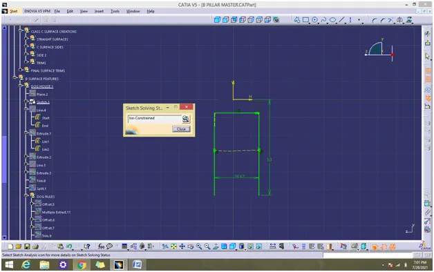
4 WAY LOCATOR
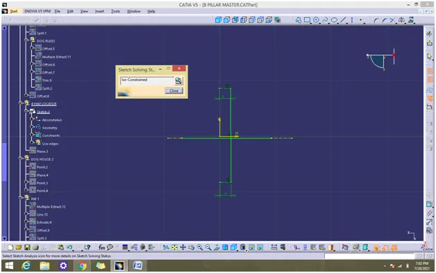
TREE STRUCTURE OF B PILLAR
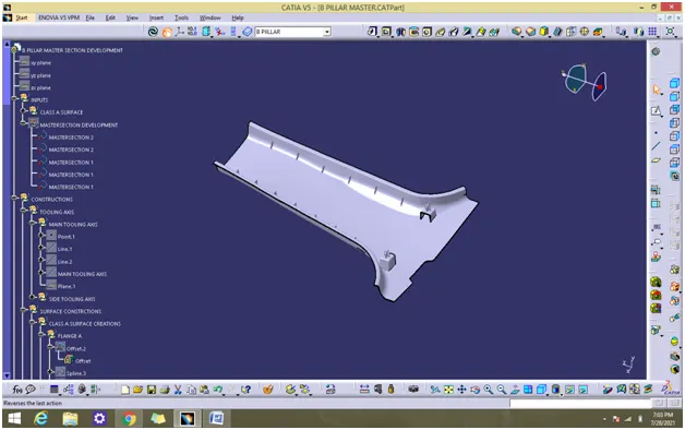
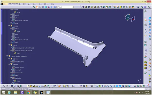
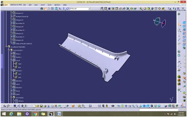
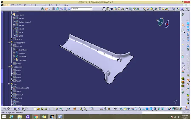
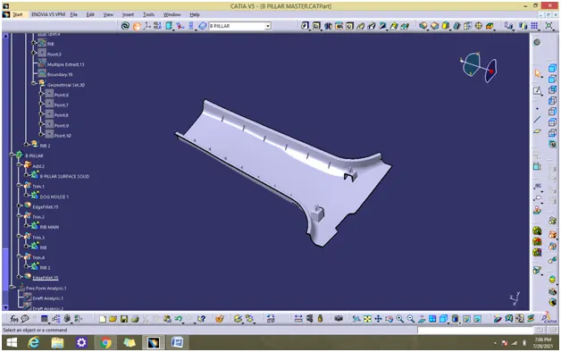
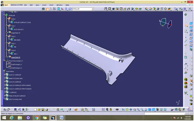
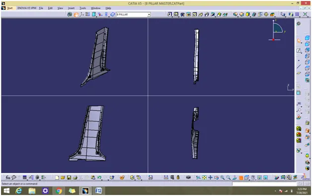
3D PART MODEL
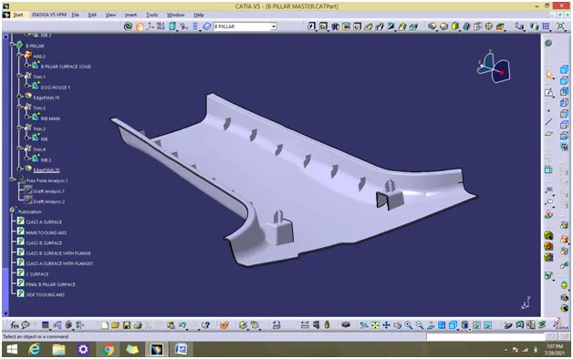
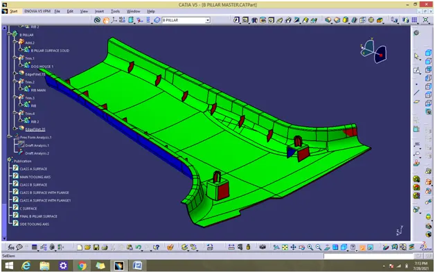
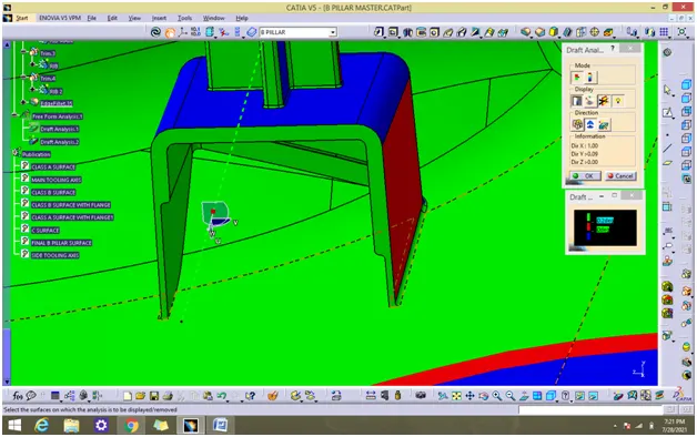
DRAFT ANALYSIS REPORT ON MAIN TOOLING AXIS
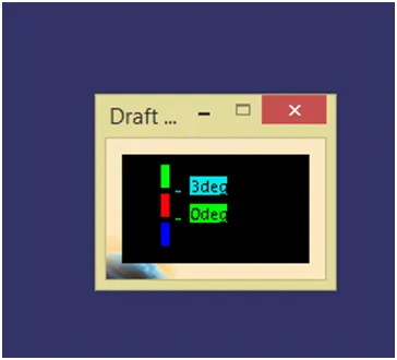
The faces which are green are more than 3 degree.
The faces which are red are between 0–3 degree
The faces which are green are more than 0.4 degree.
The faces which are red are between 0 – 0.4 degree
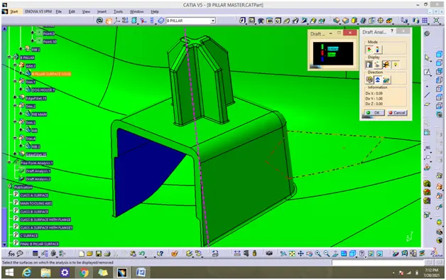
DRAFT ANALYSIS REPORT ON SIDE TOOLING AXIS
CONCLUSION
B pillar 3D models has been created by using catia v5.