Week 9 - Project - A pillar Design with Master Section
A pillar Design with Master Section
Objective –
- Create 3D CAD of A pillar from given class A surface.
- Create the proper tooling direction by following the master section to create the part that meet the requirements
- Draft analysis check to make sure that the class A surface is meeting the draft required along the tooling direction
- Creation of class B surface and class C surface by following a proper model tree structure
- Follow master section to create Attachment features
INPUT –
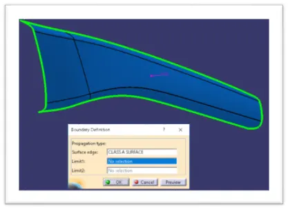
- CLASS A SURFACE -
As we know in automotive industry there are complex products that we have to design but this is not possible with simple sketches for that we need Class A Surface.
The A-surface or the styling surface is first checked for any gaps and other issues in its surfaces. This Surface acts as the input surface so any correction to be done should be with approval from the styling team or done by them. A- perfect surface is the one when a boundary is created, the lines are only on the edges of a component .
- MASTER SECTION -
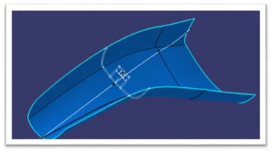
Master sections development takes place during feasibility check and concept validation stages of the product life cycle. These are typically the guides for design requirements and which decides the component packaging after the development of the concept design, i.e class A surfaces.
Master section helps us to decide the feasibility of the concept design, the clearances, the packaging and the fixation strategy of a component before converting the concept design into a solid 3D engineering design.
During the period of vehicle concept design the evaluation of the master section performance depends mainly on the reference vehicle data and experience of structure design engineer.
CREATION OF TOOLING AXIS -
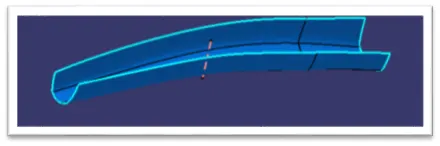
Tooling axis is the direction in which a core or cavity of mold opens. This Axis is very important to determine the orientation of the component in mold, core and cavity design.
The tooling axis is created by Bisecting line method.
DRAFT ANALYSIS OF CLASS A SURFACE -
Draft analysis of the surface is carried to check if the surface or part can be manufactured with the required draft angle.
Draft angle is needed for the component to clear the core and cavity surface as it would have shrunk towards the center while cooling.
The draft angle in this design is 3 degrees. As A surface is a single surface there won't be much difference in color. The draft analysis of A-surface is shown below.
–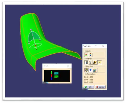
From above draft analysis we noticed that all surface area is clearing required minimum draft angle (3 degree).
CREATION OF CLASS B SURFACE –
For creating class B surface we have to offset class A surface by 2.5 mm. The offseted surface is shown below.
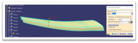
After joining all surfaces we get class B surface.
CREATION OF CLASS C SURAFCE –
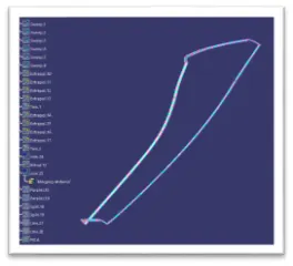
The A and B surfaces are connected by another single surface which is called the C surface.
It is created by using sweep with A surface acting as the reference surface and curve created from the boundary of the same surface.
Sweep with draft direction is also used to create C-surfaces.
The class C surface is shown below.
CREATION OF CLOSED BODY –
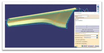
All the surfaces (A,B,C) are joined together to form a closed body.
CREATION OF ATTACHMENT FEATURE –
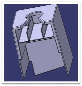
- DOG HOUSE –
General guideline for design of dog house –
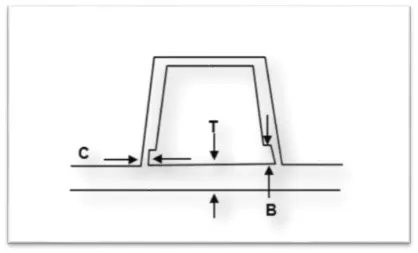
"C" is where the doghouse contacts the backside of the surface
- Doghouse wall thickness at the intersection of the part wall ( C ) should be 40% or less than the main wall stock ( T ).
- The height of ( B ) should be between 3.0 – 6.0 mm
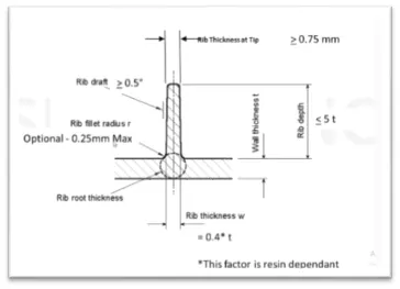
- RIB –
For creating rib for drill handle we have to considerd following rule.
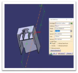
CREATION OF SIDE CORE AXIS –
DRAFT ANALYSIS ON ATTACHMENT FEATURE –
The following image shows the draft analysis of dog house with rib by considering main tooling axis and side core axis.
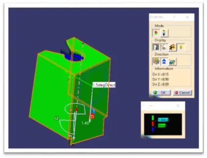
By considering main tooling axis we found that all outside surface of dog house clearing with minimum draft 1.5 degree.
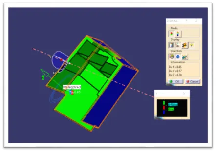
By considering side core axis we found that all inside surface of attachment feature clearing minimum draft 0.5 degree.
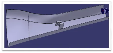
A PILLAR WITH ATTACHMENT FEATURE –
By combining attachment feature we get final part body.
DRAFT ANALYSIS ON FINAL PART BODY -
The following image shows the draft analysis of component from cavity side.
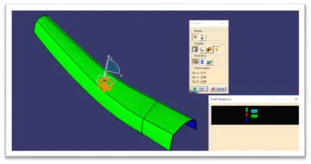
The final solid part body has to be analyzed using Draft analysis. This is done to check if all the areas of the body are satisfying the draft angle which is 3 degrees.
A draft angle is a taper applied to the vertical walls of the injection-molded component to assist with releasing the part from the mold.
Draft angles are a required feature of injection-molded custom parts. A functional part for injection molding has to have draft angles that face both the cavity and core sides. This will reduce the risk of damage to the parts and ensure that they can be ejected from the machine.