Week 9 - Project - A pillar Design with Master Section
PILLER
AIM
Create the A Pillar Plastic component through the given Class-A surface and master section and perform Draft analysis.
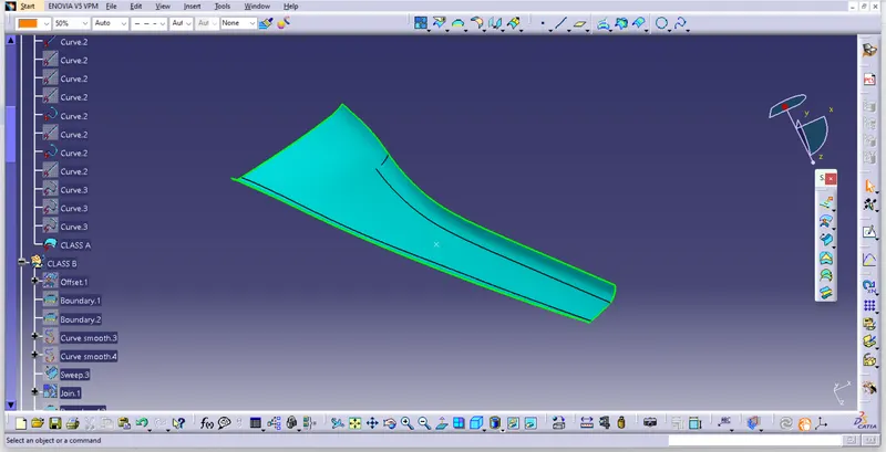
CLASS A SURFACE: Class A surface is a surface made by the designer specially in automotive design which is the aesthetic part of a body and is given as an input to the plastic designer to work on it.
- Class A surface is obtained as the input.
- Join all the surfaces to obtain Class A surface if different surfaces are given as input and ensure no gap is present between any surfaces. Thus, Class A surface is obtained and publish it. Here, the provided surface is completely joined and can be taken as class A surface.
- Publish class A surface.
TOOLING AXISS
To create the tooling axis, I used the 'bisecting' line method. Initially, I extracted two lines from the master section and then I created a bisecting line at the centre of those two lines by using bisecting line option in the line command.
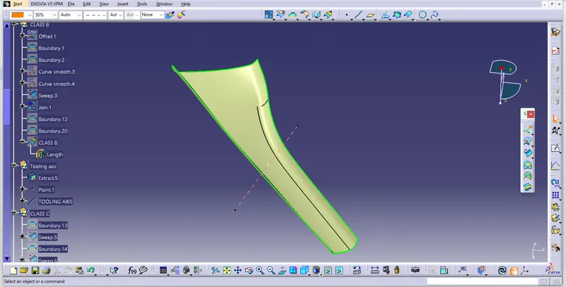
CLASS B SURFACE: It is a surface which comes below the class A surface with a particular thickness. This surface contains engineering features of a model.
- Now, Class B surface has to be created. For this surface should be offsetted for 2.5mm.
- Publish class B surface.
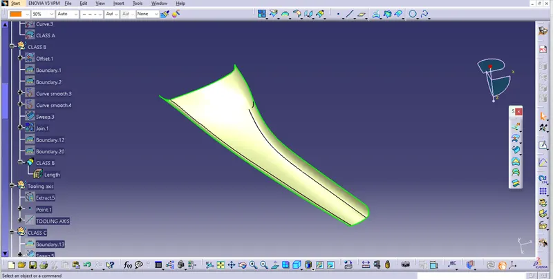
CLASS C SURFACE: It is the surface which joins class A with class B surface.
- Now class C surface has to be created and it is created from the boundaries obtained from the Class A surface. This boundary is provided as the input curve for sweep command. Using sweep command, class C surface is created.
- Appropriate sweep is the provided considering the flash and considering manufacturing procedures. Surfaces are extrapolated if necessary.
- Publish class C surface.
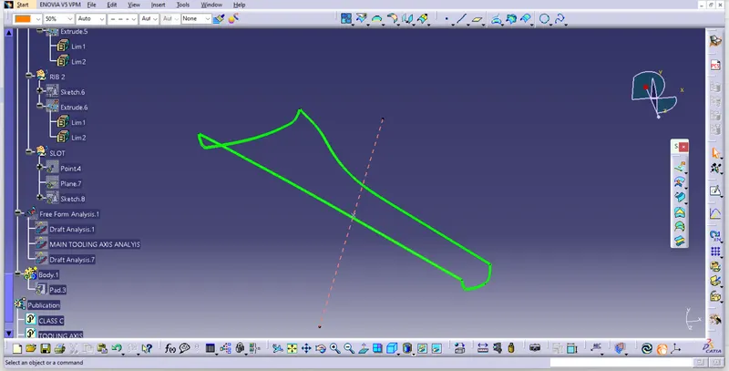
Draft Analysis Of Plastic Component
- The obtained part is draft analysed to check for the correctness of obtained model by following the draft analysis procedure mentioned above.
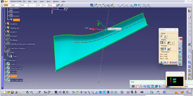
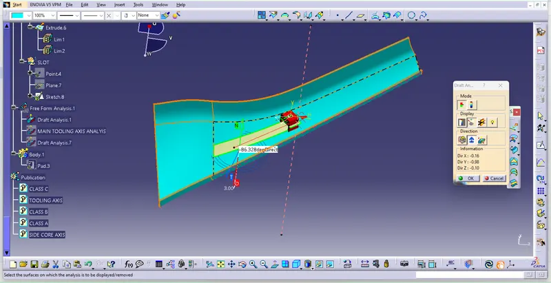
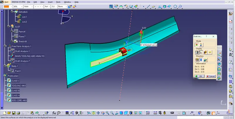
Class A Surfaces obtained are all green in color, which means that the surfaces are clearing the draft analysis. The faces that are obtained in red will be clearing in core side, as the draft direction is reversed, those red faces will be turned to green which means those surfaces are also clearing draft analysis.
Dog House creation:
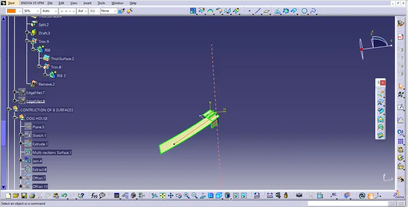
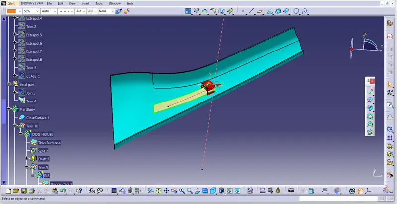
- To create the dog house on the B-side, I extracted the lines on the master section and I create a plane to extract the lines concerning the master section.
- I extracted the faces which are required to create the shell for the dog house, and I trim the surfaces with each other as per the master section dimensions.
- I created the side core access, by creating a line at the centre of the back surface by creating the point.
- I thicken the shell for mm to inside. After thickening the surface, I gave deg draft to inner surfaces of the dog house.
- After trimming the bottom cutout surface, I split the surface from the solid shell of the dog house. I gave a 0.5deg draft angle to the bottom area concerning to the side core axis.
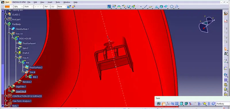
- I created the rib base and ribs concerning the master section dimensions, and I gave a 0.5deg draft angle to the rib base and ribs. After drafting the rib base, I added the rib base and ribs to the dog house shell to make a single body.
- I created a sketch for the top cutout on the dog house, and I pad the sketch to the downside and removed it from the dog house part body.
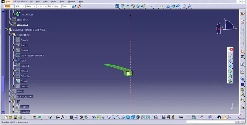
close surface
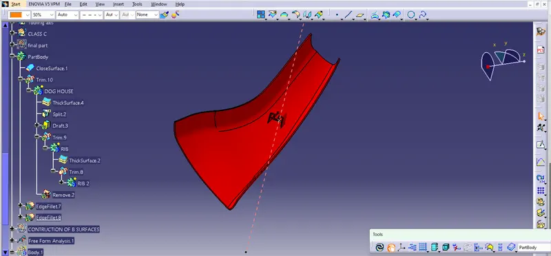
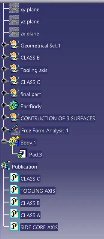
TREE STRUCTURE
CONCLUSION
- Created Tooling axis
- Created Class B and Class C surface from provided Class A surface.
- Created solid part out of surface modelling.
- Created engineering features from the master section provided.
- Draft analysis of Class A surface and final part is also done.