Week 9 - Project - A pillar Design with Master Section
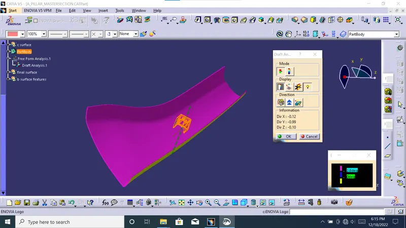
pillar master section completed into colsed body and b surface fetures are devloped. draft analayes completed with main tooling axis its giving 3deg draft angle on surfaces. dog house of the part drafted with 1.5 deg and its analayed with side core tooling axis.
The command enables youdraft analayis to detect if the part you drafted will be easily removed. This type of analysis is performed based on colour ranges identifying zones on the analyzed element where the deviation from the draft direction at any point, corresponds to specified values.
Tooling direction is the main consideration for plastic part and mould parts because it defines the movement of the mould part and the possibility of the plastic part coming out from the mould part (Core and Cavity).
In Molding, machine arrangement is given to open the mould along a direction which is known as Tooling Direction.In other words. The mould is built from two separate halves . and tooling direction basically defines the direction of mould pulls apart.Tooling direction is known as primary direction.
draft analiysing of this part completed .i created tooling axis for this part beacause of 100 presentanage draft geting this part.
No parts can be ejected from the tool if it is having a straight 90-degree profile from its base surface. A small draft angle is provided to each and every area of the component in order to get easy removal of the component from the tool.
Here we are providing a direction in which components should eject in order to get easy removal of components from the tool. In other words, it also lets us know whether the model is having a draft angle and how much is the draft angle from the tool direction.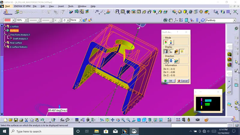
Dog house is an engineering feature used in plastic trim design. Dog houses are used as supporting feature. Sometimes other engineering features like snaps; locators etc. are mounded on them to increase their strength. Dog houses are subjected to draft analysis to prevent breakage of the component during ejection from mould cavity. Dog house and other engineering components are built on B-surface.
Thick sections waste material and are simply uneconomic. So solid shapes that would do the job well in wood or metal must be transformed to a 'shell' form in plastics. This is done by hollowing out or 'coring' thick parts so you are left with a component which regardless of complexity is composed essentially of relatively thin walls joined by curves, angles, corners, ribs, steps and offsets. As far as possible, all these walls should be the same thickness. Wall thickness guide range is 0.75 mm to 3 mm for reinforced materials 0.5 mm to 5 mm for unreinforced materials.
Tooling must be cleared for easy ejection of the component, from the core cavity. In order to clear tooling certain value of draft is given to the component. Minimum of 2-3deg is provides on all plastic components.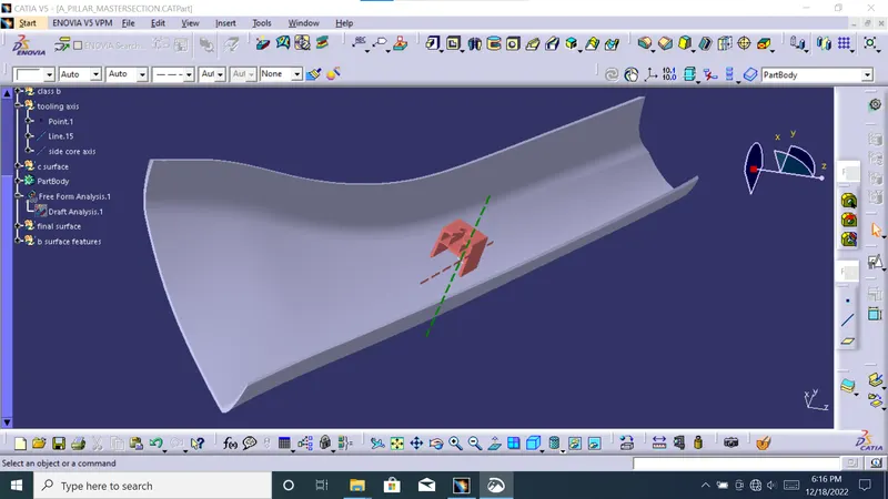
Because of the need for resin or metal to flow through the die cavity, parts that provide relatively smooth and easy internal flow paths with low flow resistance are desirable. For example, sharp corners and sudden changes or large differences in wall thickness should be avoided because they both create flow problems. Such features also make uniform cooling difficult.
Thick walls or heavy sections will slow the cooling process. This is especially true with processes since plastic is a poor thermal conductor. Thus, parts with no thick walls or other thick sections are less costly to produce.
An easy to manufacture part must be easily ejected from the die, and dies will be less expensive if they do not require special moving parts . that must be activated in order to allow parts to be ejected. Since undercuts require side cores, parts without undercuts are less costly to mold and cast.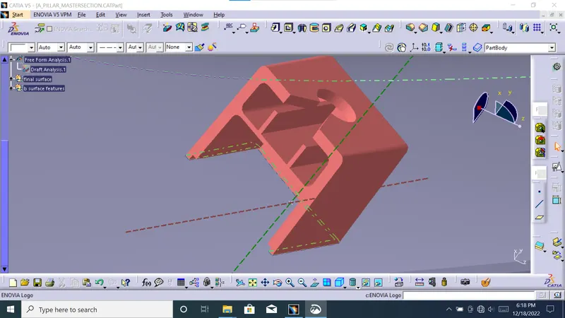
The mold is built in two separate pieces, basically. You have a Cavity side and you have the Core side. The Core pulls apart from the Cavity and that's the Dyeline or the Tooling Direction.
Connectivity of Class-A surface: Checking the connectivity of the surface, this can be done by creating boundaries or by simply using the join option such that any openings can be easily visualized.