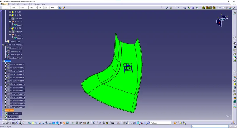
Week 9 - Project - A pillar Design with Master Section
Week 9 - Project - A pillar Design with Master Section
OBJECTIVES:
- To create the class B and class C surfaces from the given class A surface
- To form a solid geometry by combining all the surfaces
- To create a dog house for the solid part whilst following the design rules
- To perform draft analysis on the class A surface and the solid part model
MASTER SECTION:
Master sections are the guides for design requirements which decide the component packaging after the styling surface.
PRE-DESIGN CHECKS:
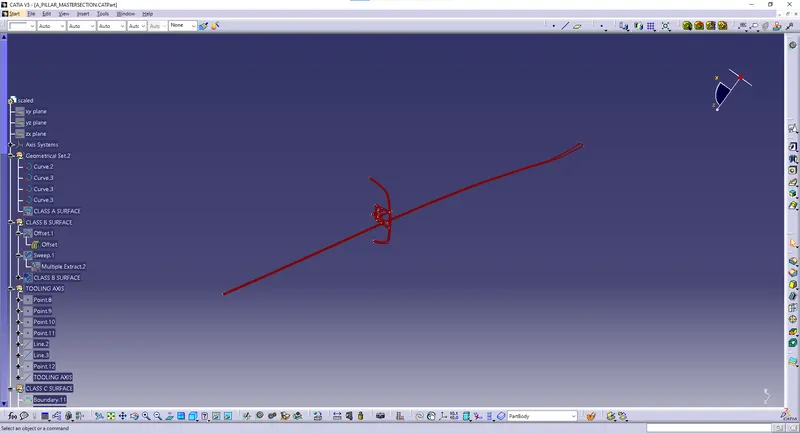
Before starting the creation of the class B surface we must ensure that the given class A surface is properly closed and the surface continuity is proper. This can be done either with the help of the join operation or by using the boundary feature.
TOOLING AXIS:
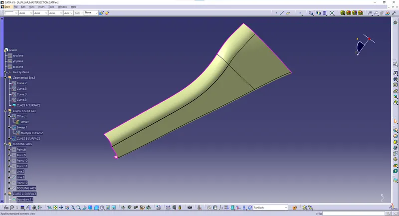
- The next step is to create the tooling axis for the part which will determine the direction in which the core and cavity of the mould will move.
- Designer must ensure that all holes and slots are covered in the main tooling and thus side core must be avoided whenever possible
- After analysing visually for the best possible tooling axis, an reference tooling axis is created on the centre of one of the surfaces of the A pillar trim.
- The main tooling axis is created by using the bisecting method and by taking references from the master section.
DRAFT ANALYSIS:
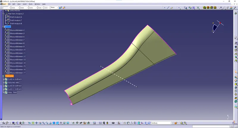
- Draft analysis is done on the class a surface after the tooling axis has been obtained
- The part must have a minimum draft angle of 3 degrees on all the tapered faces
- Using the feature draft analysis tool and the compass the part surface is validated for the minimum draft criteria.
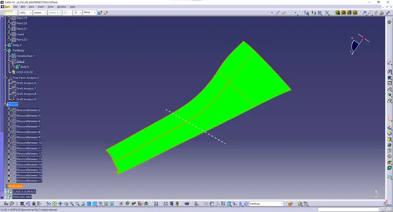
CLASS B SURFACE
- After all the validation has been done, the class B surface is created by offsetting the class B surface to a distance of 2.5 mm
- After offsetting a large opening in the surfaces is found which is closed with the help of sweep and multi section commands
- The class B surface is then extrapolated in parts to trim it along with the class C surface.
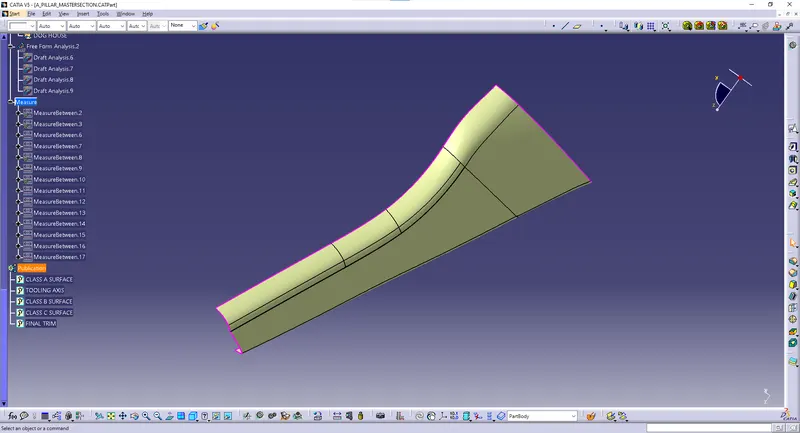
CLASS C SURFACE
- The class C surface which connects the class A and class B surface is created by sweeping the boundary of the class A and using the class A as a reference.
- The sweep is divided into several parts in order to avoid complexity
- Surfaces which are parallel to the tooling direction are swept with the tooling axis as reference and with a draft angle of 3degrees.
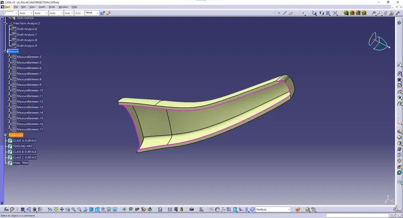
DESIGN OF DOG HOUSE:
- The two main purposes of a dog house are to avoid sink marks and to house various other engineering features like screw boss, locators etc.
- The dog house should follow certain design rules which are stated below.
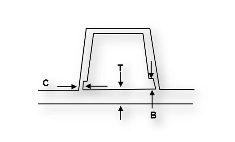
- Doghouse wall thickness at the intersection of the part wall (C) should be 40% or less than the main wall stock (T).
- The height of ( B ) should be between 3.0 – 6.0 mm.