Week 9 - Project - A pillar Design with Master Section
Aim:
To create a Class B and C surface with the help class A surface and to create the engineering features with the given master section.
The operation to do:
- Create Tooling Axis.
- Create Draft Analysis for Class A Surface.
- Create Class B Surface.
- Create Class C Surface.
- Create a Draft Analysis for the Overall Surface.
- Create Closed Surface.
- Create Dog House.
- Create Locators.
- Check draft analysis for Dog house and locators.
The material used in A - Pillar :
-
Acrylonitrile Butadiene Styrene (ABS).
Why this material is used?
- ABS has a low melting point, enabling its easy use in injection molding and 3D printing. It also has high tensile strength and is very resistant to physical impacts and chemical corrosion, which allows the finished plastic to withstand heavy use and adverse environmental conditions.
- High dimensional stability (Mechanically strong and stable over time)
- The high surface brightness and excellent surface aspect.
Where it is used?
- The forward-most roof pillar, forming the uprights that support the windscreen. The pillars are named alphabetically by order of placement from front to back of the car.
What is master section?
- Master Section are the guide lines given by the packaging department, who is common to both the plastic and sheetmetal designers. They will alloate the place for Engineering features.
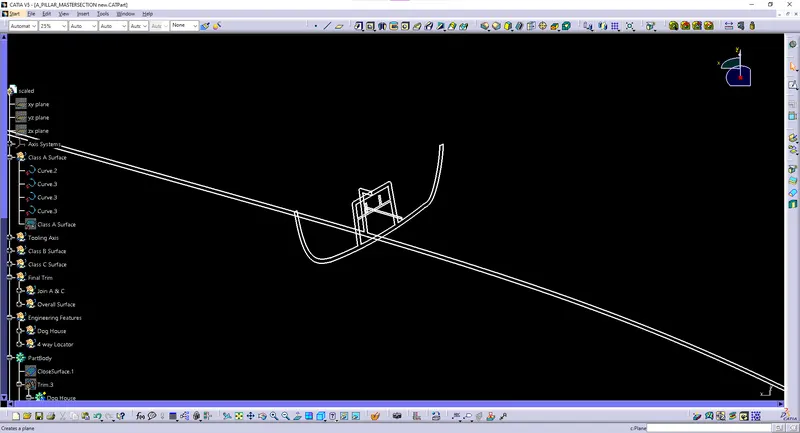
Do's and Dont's in Master Section:
- The guide lines should not be taken as reference, and Extraction of line should not be done.
- The sketch should not depends on the master section.
- To take reference we can take point along guide lines and the point should be isolated before using it.
Followed Constraints:
- The change in dimension of the Class A Surface is not allowed.
- Change in thickness is not allowed.
- The thickness given to the A - Pillar is 2.5 mm.
Tooling Axis:
- The tooling axis for this component will be created from the Bisecting metod, since the master section is not belongs to any other axis. This should be done by creating a point along the master section of dog house at two lines. And the points are isolated from the master section and the lines are created according to the points created in the master section. By selection the two lines as reference and selecting the point will create the tooling axis in the bisecting method.
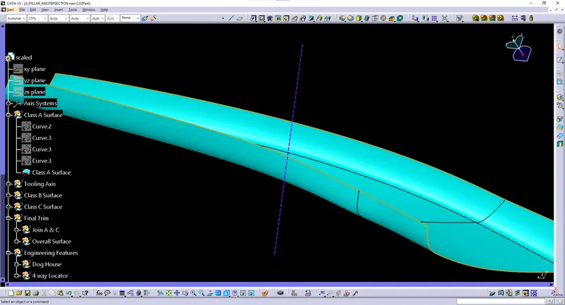
Class A Surface:
- Class A Surface is a scanned model or the model which is already drawn is given for further process. It describes the final production surface data for the aesthetic parts of the car. The term 'Class A' is often misunderstood, but it's generally seen as the 'Holy Grail' of surface modeling. This is the outer layer of the model.
- Given Class A surface is in .igs part file. We have to join the model in the .CATPart file to create a Class A Surface.
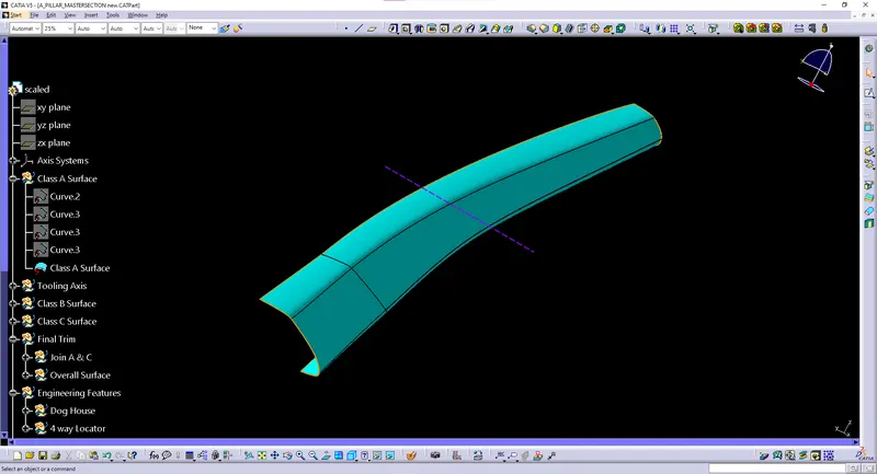
Class B Surface:
- This is the surface followed by Class A Surface. It is the inner surface of the model with some thickness. The fillet and offset of the Surface should be given according to the Class A model. The flash from the molding process should not come into the surface of Class A, so the Class B design should not disturb the class A Surface.
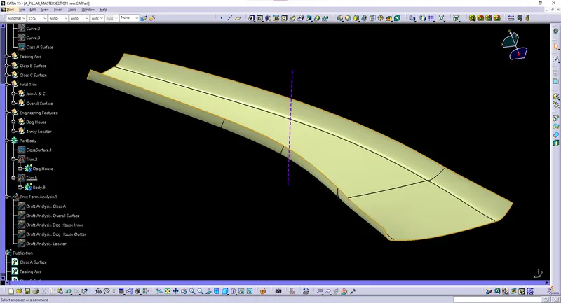
- We have to create an overall offset for this A - Pillar. After this, we need to do multi section for the patched surface to create the closed surface for class B.
Class C Surface:
- Class C Surface is the surface that joins both class A & B using the boundary, trim, join method. The Class C finish allows more imperfections than Class A or B. Class C is often specified for interior surfaces not readily visible, surfaces that will be covered by another part when assembled, or surfaces that the Customer feels do not need to meet a high cosmetic.
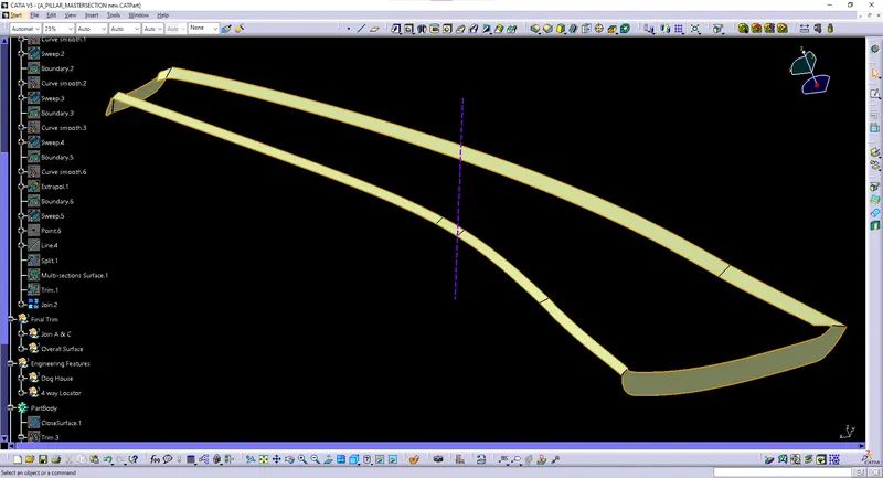
- This Class C Surface is taken from the Reference of the Class A Surface. with an angle of 90 deg for the both Outter A - Pillar surface and Window switch surface. The top shoud be given a angel of 3 deg.
Final Product:
- The final product includes the finished surface of Class A, Class B, and Class C. Having the complete surface model of the A - Pillar.
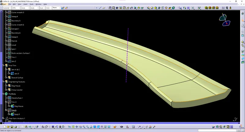
Join A & C
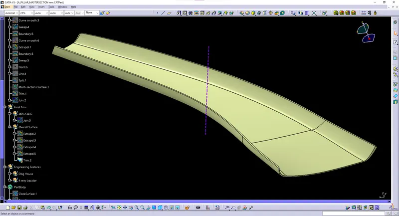
FINAL TRIM
DOG HOUSE:
- Dog house is an engineering feature used in plastic trim design. Dog houses are used as supporting feature. Sometimes other engineering features like snaps; locators etc. are mounded on them to increase their strength. Dog house wall thickness at intersection of part wall (c) should be 40% or less than main wall stack (T).
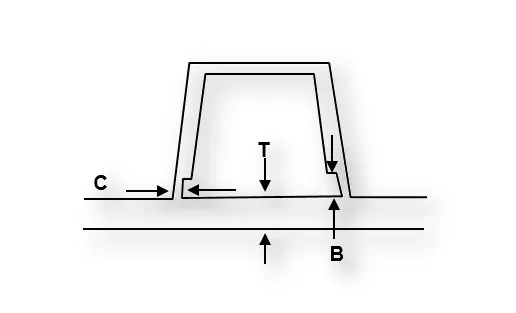
Guidelines to create Dog House:
- Width of the DogHouse - (25 - 35mm).
- Height of the Dog House - (45 - 60mm).
- Outter Draft - (> 0.3 deg), Nominal = 1.5 deg.
- Inner Draft - (> 0.1 deg), Nominal = 0.5 deg.
- Thickness - Nominal Wall thickness.
- Height of the Sink mark cut - (3 - 6mm).
- Fillets can be given according to the thichness rule.
- Width of one dog house to another dog house is (w x 3).
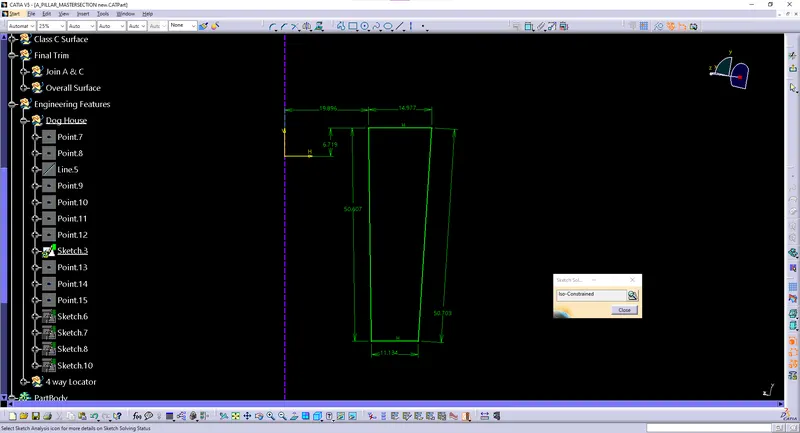
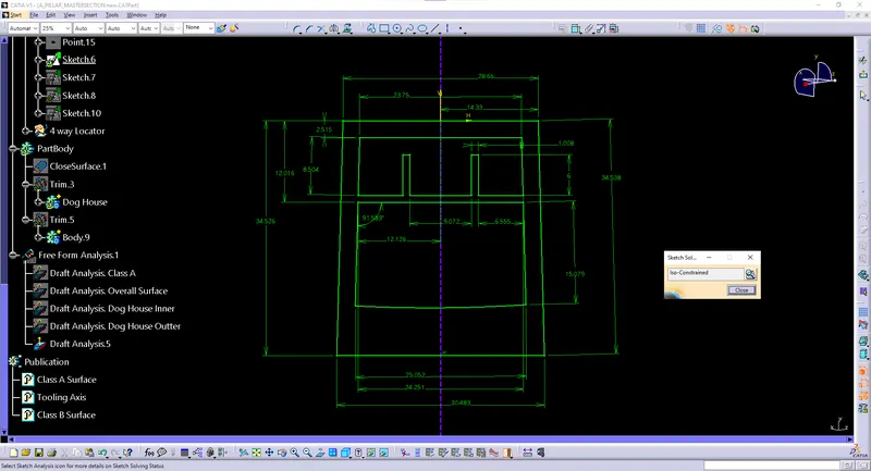
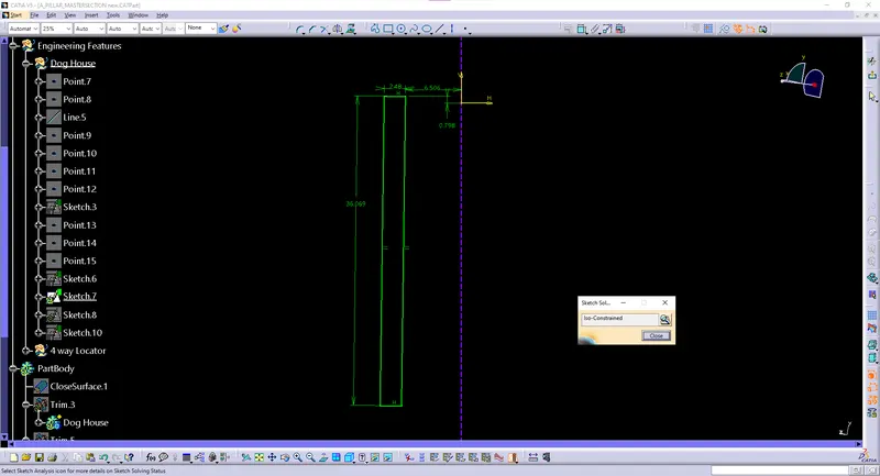
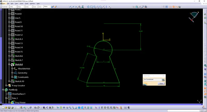
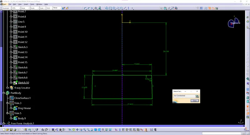
Sketch of Dog House

Dog House
LOCATORS:
- The device to establish and maintain the position of the workpiece in work holders such as jig and fixture to ensure repeatability of work holder. The locating device for a work holding device mainly depends on the property of workpiece and the overall machining process.
- Types: 2- way locator, 4- way locator.
- 2 - way locator consist of ribs for support.
Guidelines to create Locators:
- Thickness - 2 mm
- Chamfer - Nominal value - 5 x 45 deg.
- Height - > height of Heat Stakes.
- Width - 22 mm
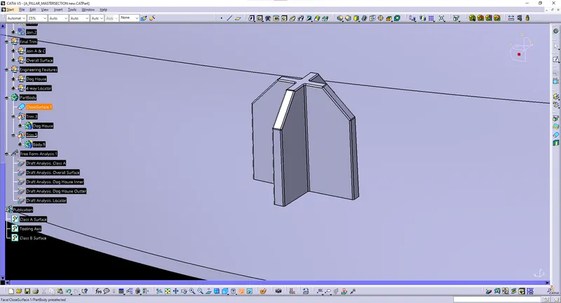
4 - way locator
Draft Analysis:
- The draft analysis technique is used to analyze whether our part model created in CAD is manufacturable based on the draft condition applied. Here the part should get easily removed from the panel dies (in case of Sheet metal part) or Mold (in case of plastic). The analysis shows whether the angle given on the surface is up to the level or not. This can be identified by using Green, Blue, and Colour. Green means to perfect (< 2.9deg), Blue (0deg), and Red (> 2.9deg). These degrees will cange for engineering features.
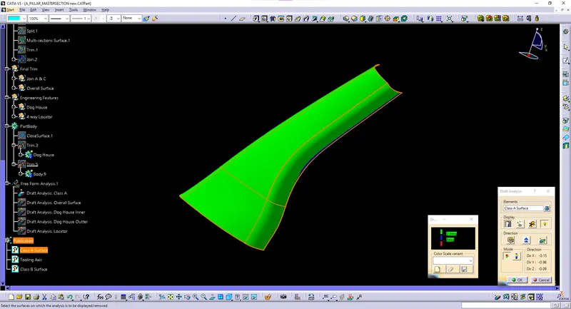
DRAFT ANALYSIS OF CLASS A SURFACE
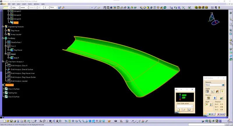
DRAFT ANALYSIS OF OVERALL SURFACE
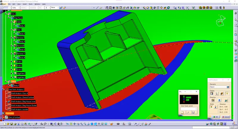
DRAFT ANALYSIS OF Inner Dog House
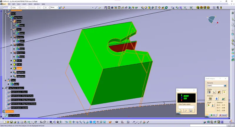
DRAFT ANALYSIS OF Outter Dog House
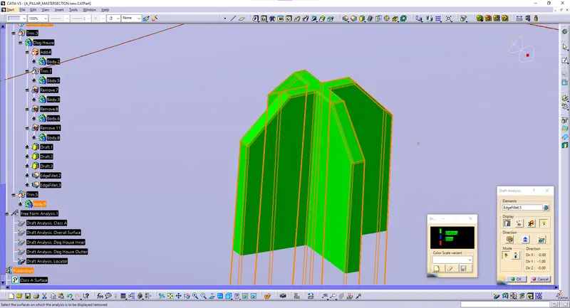
DRAFT ANALYSIS OF Outter Dog House
Solid Surface:
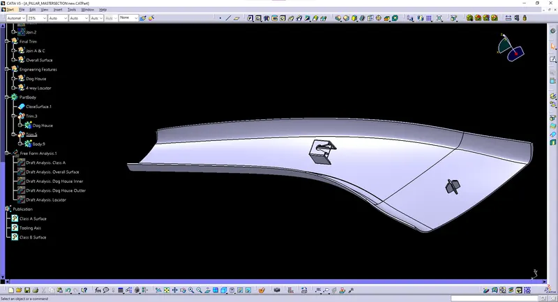
FINAL OUTPUT
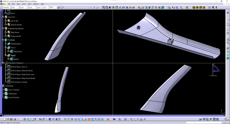
MULTI-VIEW
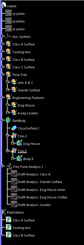
FAMILY TREE