Week 8 - Challenge 1 - Base Bracket Design
Aim: To create the Base Bracket Plastic component through the given Class-A surface. To begin with, the tooling axis for the given Class-A Surface should be created meeting the requirements of the draft angle and at the end perform the Draft analysis on the model.
Operation to do:
- Create Tooling Axis.
- Create Draft Analysis for Class A Surface.
- Create Class B Surface.
- Create Class C Surface.
- Create Final Product.
Material used in Base Bracket:
Plastic Base brackets, which have lower hardness and stiffness, also exhibit a cyclic softening effect in their stress–strain characteristics. Material used in Base Brackets are.
- Thermoset Plastic.
Where it is used?
- It is used in the hydralic cylinder mounting area in the car bonet.
Followed Constrains:
- The change in dimension of the Class A Surafce is not allowed.
- Change in thickness is not allowed.
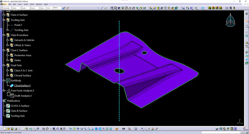
Tooling Axis:
- The direction in which the core and cavity opens for molding process is called tooling axis. The direction in which the surface is created is called tooling axis. For our convinent we can change the colour and size of the line for easy identiication. For the Base Bracket the tooling axis direction is along Z.
Class A Surface:
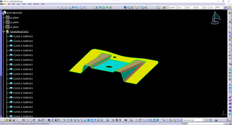
- Class A Surfaxce is a scaned model or the model which is already drawn is given for further process. It describes the final production surface data for the aesthetic parts of the car. The term 'Class A' is often misunderstood, but it's generally seen as the 'Holy Grail' of surface modeling. This is the outer layer of model.
Draft Analysis:
- The draft analysis technique is used to analyze whether our part model created in CAD is manufacturable based on the draft condition applied. Here the part should get easily removed from the panel dies (in case of Sheet metal part) or Mold (in case of plastic).
- The analyse shows whther the angle given in the surface is upto the level or not. This can be identify by using the Green, Blue and Colour. Green means to perfect (< 2.9deg), Blue (0deg), Red (> 2.deg).
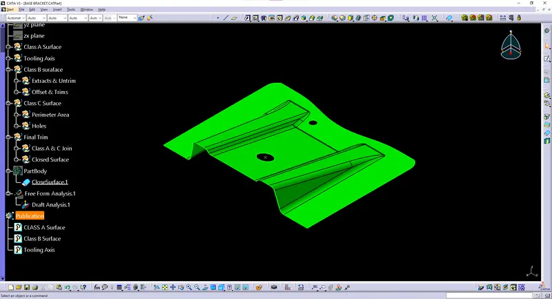
DRAFT ANALYSIS OF CLASS A SURFACE
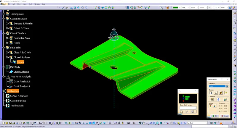
DRAFT ANALYSIS OF OVERALL SURFACE
Class B Surface:
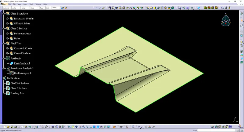
- This is the surface followed by Class A Surface. It is the inner surface of the model with some thickness. The fillet and offset of the Surface shoud given according to the Class A model. The flash from the molding process shoud not come in the surface of the Class A, so the Class B design shoud not distrub the class A Surface.
Class C Surface:
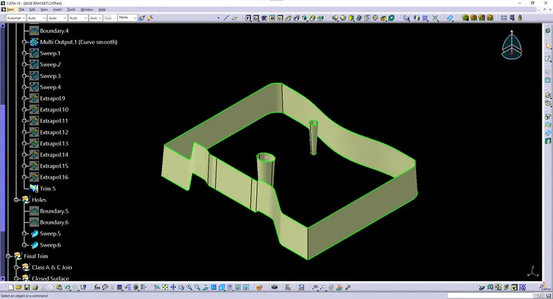
- Class C Surface is the surafce which join both the class A & B uisng the boundary, trim, join method. The Class C finish allows more imperfections than Class A or B. Class C is often specified for interior surfaces not readily visible, surfaces that will be covered by another part when assembled, or surfaces which the Customer feels do not need to meet a high cosmetic finish.
Final Product:
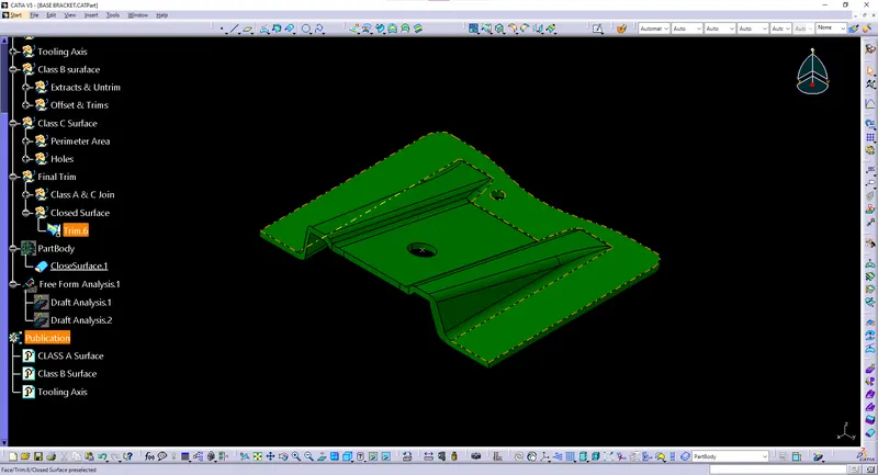
- Final product includes the finished surface of Class A, Class B and Class C. Having the complete surface model of the Base Bracket.
FINAL TRIM
Solid Surface:
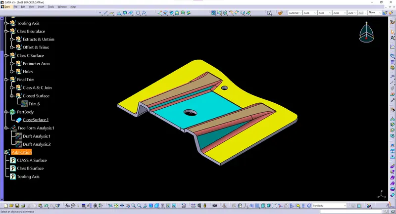
After the completion of the final trim it shoud be change to the Close surface.
CLOSED SURFASE
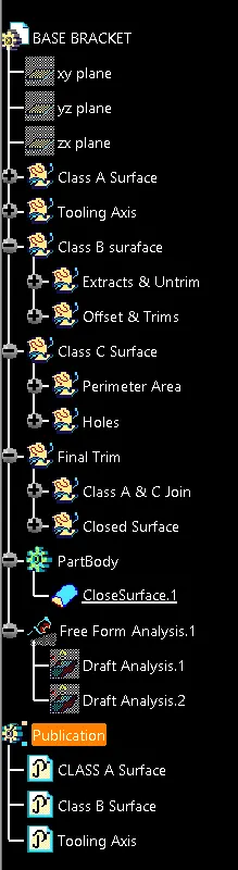
Family Tree