Week 9 - Project - A pillar Design with Master Section
A pillar Design with Master Section
MASTER SECTION:
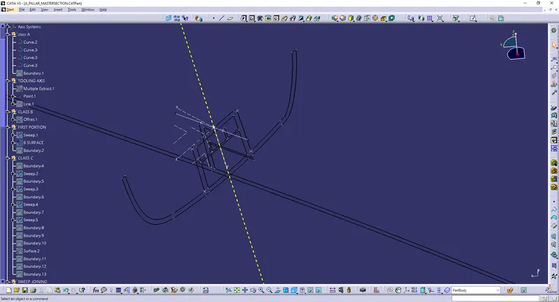
- Master sections are the guides for design requirements that decide the component packaging after technical (Styling, Concept, or Class-A) surfaces.
- This helps you to decide the feasibility, clearance, packaging, and fixation strategy before working it on a 3D.
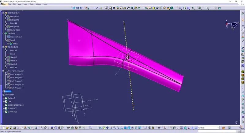
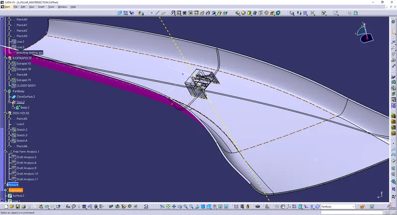
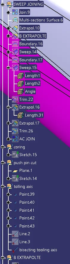
TOOLING AXIS WITH BISECTING METHOD : Tooling axis means the direction in which core and cavity open and close.Tool is nothing burt mold, tooling axis is created to know in which direction the mold open and close, parts drafts are given along this axis.
MATERIAL SELECTION AND REASON FOR SELECTING THAT PARTICULAR MATERIAL :
A PILLAR Made of highest quality ACRYLONITRILE BUTADIENE STYRENE (ABS) materials.
REASON FOR CHOSSING ABS MATERIAL:
- High rigidity.
- Good impact resistance, even at low temperatures.
- Good insulating properties.
- Good abrasion and strain resistance.
- High dimensional stability (Mechanically strong and stable over time)
- High surface brightness and excellent surface aspect.
MANUFACTURING PROCEDURE :
Injection Molding
It is a manufacturing process used for the mass production of plastic components. It works by injecting molten material(plastic) into a mold. Under the application of heat and pressure, the material solidifies into the required shape. Once the product cools, it is ejected from the mold with the help of ejector pins.
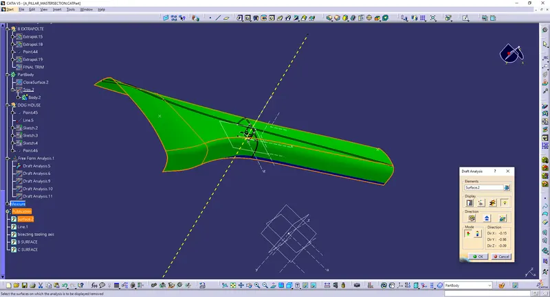
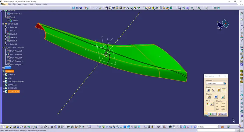
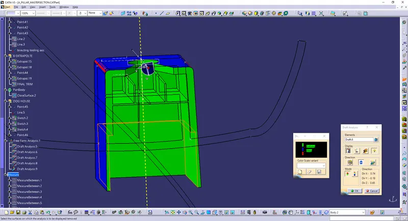
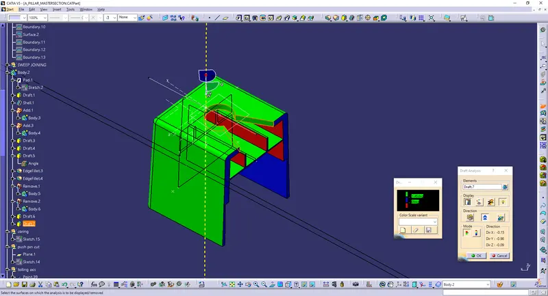
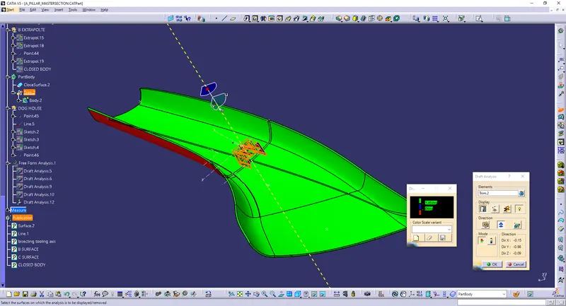
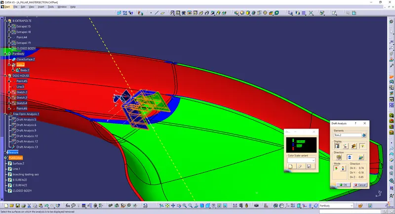
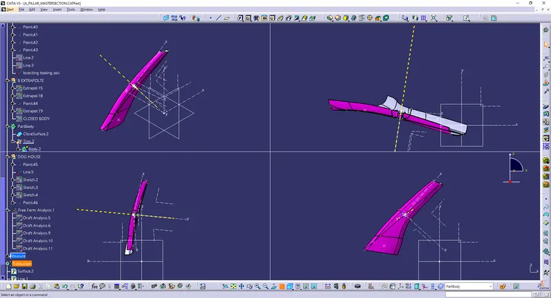
DRAFT ANALYSIS : Draft analysis is done to check weather the tooling axis and draft angle are correct or not and to find weather the component is manufactured and ejected or not. Draft Analysis is a tool in CATIA which identifies the zones which deviates from the specified values of angles along a defined draft direction using colour codes.
DRAFT ANALYSIS 1
DRAFT ANALYSIS 2
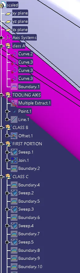
CLASS A SURFACE : Asurface is the aesthetic surface created by the class-A engineer. It is the visible aesthetic surface of any automotive component. class A surface is any of a set of freeform surfaces of high efficiency and quality.
CLASS B SURFACE : B surface is the offset of the class A surface. Class B surfaces are Engineering Surfaces which are invisible to the eyes or often on the back side of the Class A surfaces. It is mainly the thickness of the component or Class A.
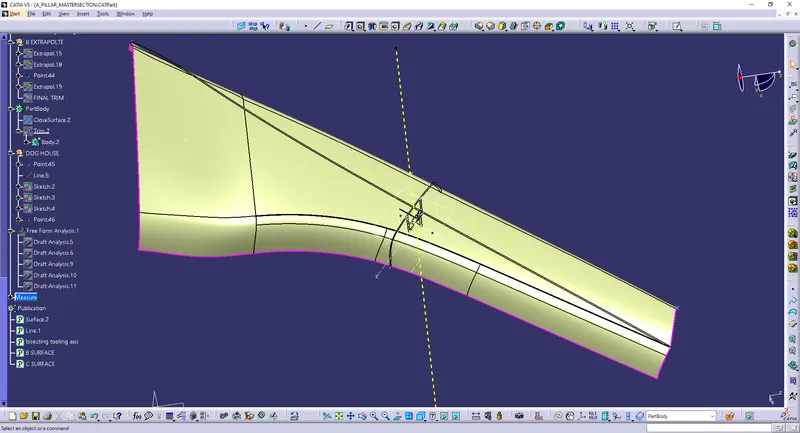
CLASS C SURFACE : C surface is joining surface between A and C. Class C surfaces are connectors between Class A and B surfaces. This surface connects both A and B surfaces along the Tooling Axis. It contains the draft as per the design. Its is basically the thickened surface between both A and B surface.
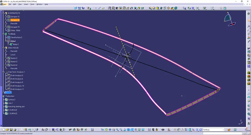
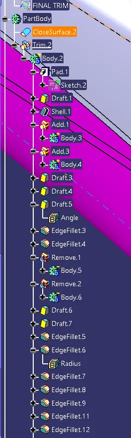
CLOSED SURFACE BODY
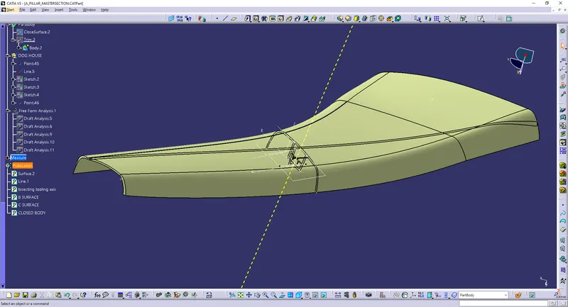
SOLID BODY
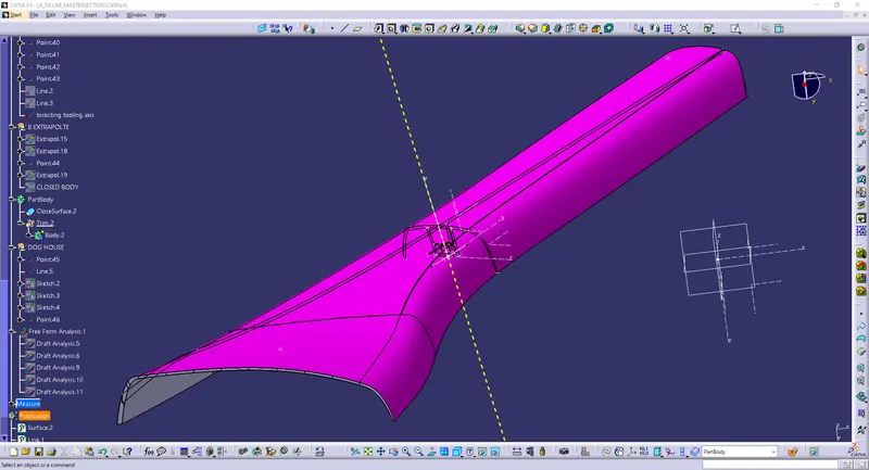
DOG HOUSE
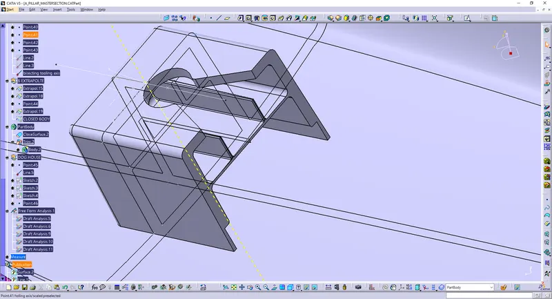
Dog house is an engineering feature used in plastic trim design. Dog houses are used as supporting feature. Sometimes other engineering features like snaps; locators etc. are mounded on them to increase their strength. Dog houses are subjected to draft analysis to prevent breakage of the component during ejection from mould cavity. Dog house and other engineering components are built on B-surface.
GUIDE LINES OF DOG HOUSE
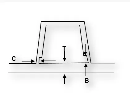
C- is where doghouse contacts back side of surface.
Dog house wall thickness at intersection of partwaqll(c) should be 40% or less than main wall stock(T).
Height of (B) should be between 3-6mm.
dog house draft outer faces -1.5 degree
dog house inner face draft-0.5-1 degree
Coring or sink mark cut 3-6mm
height of the dog house is 60mm
dog house outside fillets -3.5mm
dog house inside fillet- 1mm
CONCLUSION
This project imparted a great deal of knowledge regarding the creation of tooling axis and performing proper draft analysis on a component which are essential steps to ensure a design is fit for manufacture. It also provided valuable insights on the design of a plastic component using Class A, B and C surfaces using CATIA.