Week 9 - Project - A pillar Design with Master Section
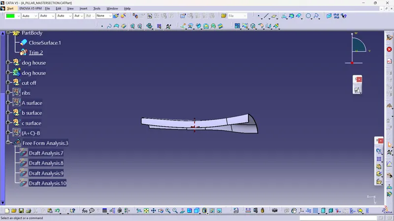
STEP 1- After receiving pillar and master section as input, we check the connectivity of our class A surface using boundary command.
Since their is no gap, we start our 2nd step.
MASTER SECTION - Master section are the guides for design requirement which shapes the components and will tell you following things
- Clearance with Driver manikin
- Check all the mechanism
- All the function component should be inside rezone.
- Packaging of components
- Fixation strategy
Step 2 - Creating Main tooling Axis
The direction in which core and cavity open is tooling axis.
- We have received master section, there is a B-feature(dog house) in master section.
- Both Dog house and pillar will have same tooling axis in main direction.
- So, I have used bisecting method for making tooling axis.
- So make a point in middle of line and make a 2 lines using point-point in master section, and make bisector of these lines , the bisecting will our main tooling axis
Step- 3 Draft analysis for CLASS A -Surface
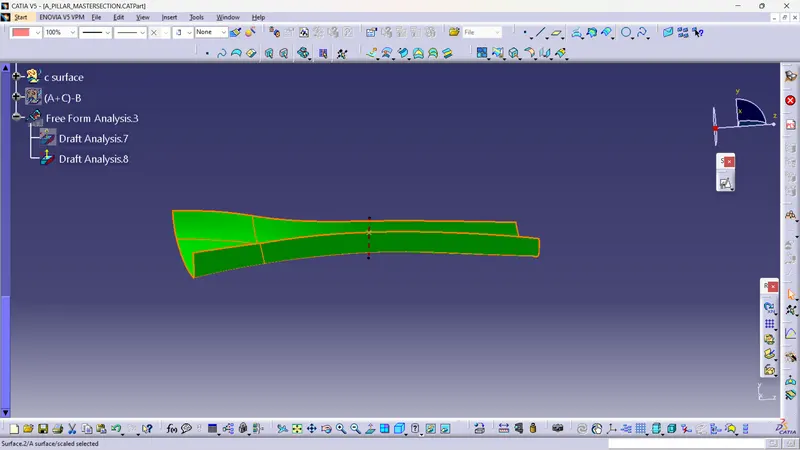
- Click on Insert > Analysis > Features draft analysis
- Make sure it should be in material mode
- Now go to direction, and click 2nd option.
- Pick the compass and align it with the tooling Axis and click on the lock .
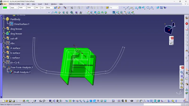
- Now click on the class A surface,we will see a green colour surface.
Class A which is green in draft analysis shows it is clearing but at corner the class is not clearing
Step-4 Creation of Class-B Surface
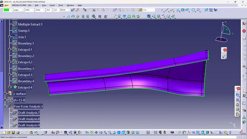
- With the help of master section we can tell that our thickness of part is 2.5mm.
- So offset Class A surface 2.5 mm.
- Now extract the edges using boundary command and fill the patch using sweep with reference surface command.
- Join them and class B is obtained.
Step-5 Class-C Surface
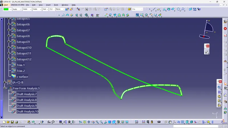
- To create C- surface I have used sweep using draft diection and reference surface.
- Use boundary to extract the boundary of edges, and use sweep using draft direction
- Simalarilay fellow same steps for other side, using reference surface
- Extrapulate the corner egdes of Class C surface and trim them,we get our class C surface
Class C- surface
- Join with class A
- Now to get Final surface we need to extraoulate some edges of Class B
- So after extrapulating of class B, trim it with above Join, we will get CLASS A+B+C.
CLASS A+B+C
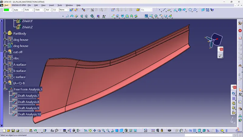
- Go to part design workbench and a solid part body using the close surface command.
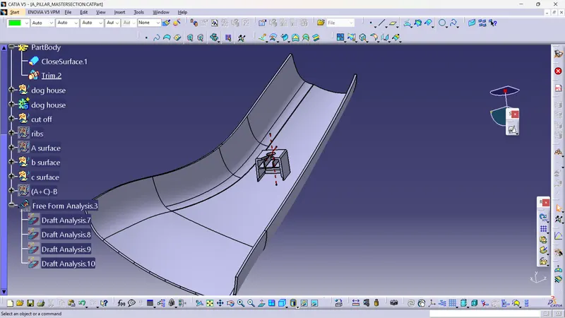
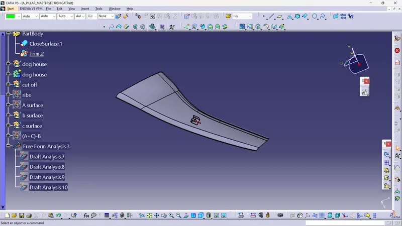
Step -6 Draft analysis report for the pillar without engineering features
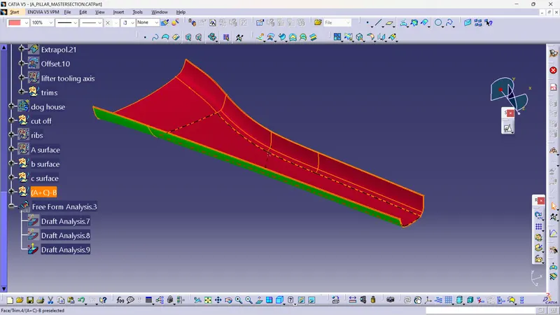
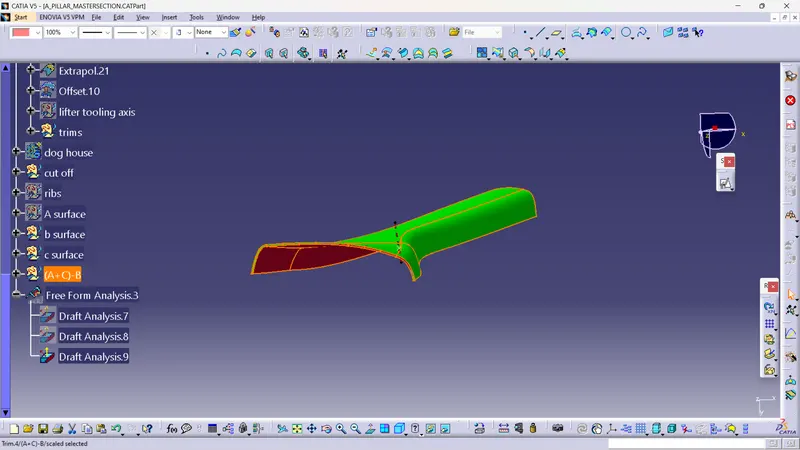
Draft analysis tell whether our component is manufacturable or not, if it's green it clears but if it's red means the surface is not clearing.
- All the area which is green means a draft 2.9 or above is given.
Step -7 Creation Of Attachment features
DOG HOUSE- A dog house is a feature that is used
- to avoid sink marks
- solve length issue of screw boss
- and with the dog house we can make screw boss perpendicular to tooling axis.
CONSTRUCTION OF DOG HOUSE
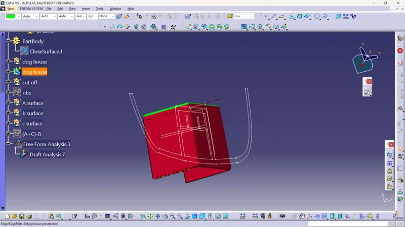
- With the help of master section we will create our dog house.
- First i have made a axis system
- Now i have used a sketch using positioned sketch in ZX plane.
- Now i have used sweep using draft using sweep direction and angle is 1.5degree and direction is tooling axis
- Now using Multi section , I have filled above part and join them
- And used thick surface command from part workbench also thickness of this is 2,5mm(given in master section).
- Now i have extract back face of above image and extrapolared it.
- Offset it 29.2mm , Spilt the front part of thick surface, to get proper front face
- Split lowerv part with pillar.
CREATION OF LIFTER TOOLING AXIS
- Since we have used sweep using draft direction so we do not need to provide draft in main tooling axis but we have to provide draft in side core axis.
- To create Lifter axis a have fellow this method.
- I have made my tooling axis with the help of above roof.
- Extract the roof face of the dog house
- Now make a point a cente of the surface and another point at edge of extract in the middle and now draw a line using these 2 points and this line will be lifter tooling axis
CONSTRUCTION FOR LOWER THICKNESS C
- Before creating Lower cut provide the draft
VALUE OF C = 0.4*2.5=1mm
so we will offset it 1.5 mm outside.
- Extract 3 inside walls of dog house and extrapolate it
- now offset in outside direction 1.5mm.
- Now extract upper surface and extrapolate it.
- Offset 19.5mm (the valve of B may vary becuse of the pillar surface).
- Trim both the offset.
- Now split this trim with dog house and our dog house structure is made.
CONSTRUCTION FOR UPPER CUT.
- Extract the above roof surface and make a point i centre of that extract and create a plane
- Extrude it and take tooling axis as direction
- extrapulate the extrude so that it will cut Dog house properly.
- Use split to cut the upper roof and provide draft(1.5 degree) to cut part..
- Provide the fillets =0.25mm
CONSTRUCTION FOR CENTRE BASE WITH 2 RIB
FOR CENTRE BASE
- With the help of master section I have mase line and make sure it is little larger than dog house
- Extrude the line in lifter direction
- this is base, we will provide the thickness.
SO TO PROVIDE THE THICKNESS I HAVE TAKEN THICKNESS DIMENSION (1.5mm) FROM PDF
- After providing thickness , i have used split to give it proper shape
- Now provide draft as shown in below image
FOR 2 RIBS
- Multi Extract the line from master section(below image)
- Extrude in direction of lifter axis and extrapolate both
- Also extract the base and egdes of base
- now extrude both lines and extrapulate the base extract
- Trim both Rib separately.
- Now use close body command
- Provide the draft (0.5degree) and fillets, add to base body
- Now union trim this body to DOG HOUSE BODY and provide the fillets(0.25mm)
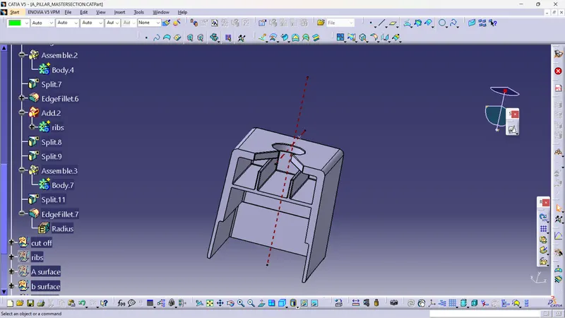
(ABOVE PIC IS FINAL B SURFACE)
- Now add dog house body with pillar body and our output is ready.
STEP8- Draft analysis report for the DOG HOUSE AND FINAL COMPONENT