Week 9 - Project - A pillar Design with Master Section
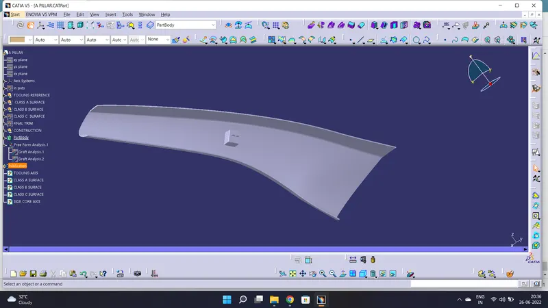
DESIGNING A PILLAR USING MASTER SECTION
OBJECTIVES
- To improvise the Class A surface by resolving bad patches and adding flanges to it.
- To create A pillar solid model with the help of improvised class A surface.
- To create B side features for the A Pillar using the master section given to us as an input.
- To create main and side core tooling axis for A pillar and its B side features.
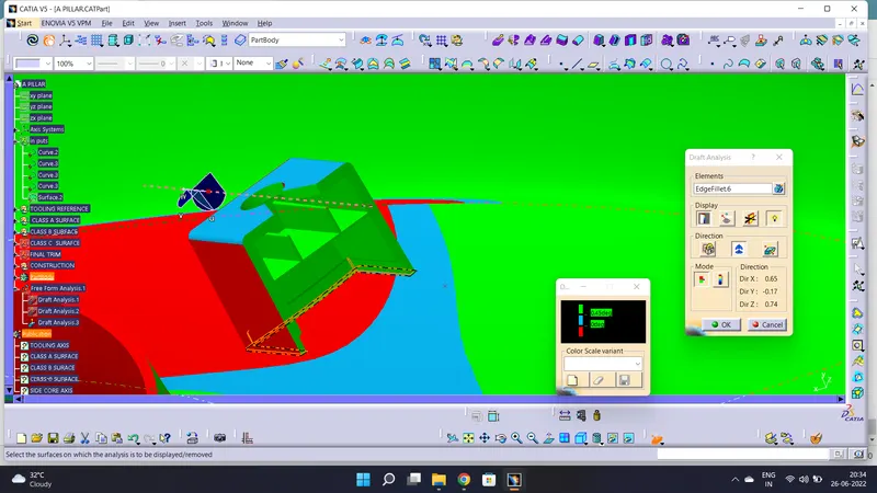
- To do the draft analysis of the overall model of the A pillar i.e including B side features.
INTRODUCTION
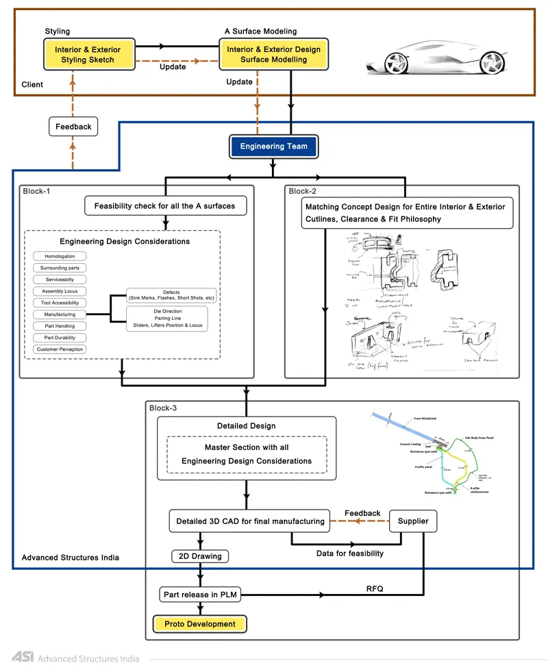
MASTER SECTION: Master sections development takes place during feasibility check and concept validation stages of the product life cycle. These are typically the guides for design requirements and which decides the component packaging after the development of the concept design, i.e class A surfaces.
Master section helps us to decide the feasibility of the concept design, the clearances, the packaging and the fixation strategy of a component before converting the concept design into a solid 3D engineering design.
During the period of vehicle concept design the evaluation of the master section performance depends mainly on the reference vehicle data and experience of structure design engineer.
DESIGNING METHODOLOGY:
IMPROVING THE CLASS A SURFACE
The given class A surface is not a proper surface because it is lacking the side flanges so first thing that we have to do is to create the flanges on both the sides of the class A surface.
For creating flanges we will first extract the side edges of A surface and the surfaces touching these edges.
Finally we'll apply the sweep command using the "with reference to the surface" option and join the resulting edges with A surface using trim command.
Make sure that the resulting flanges are properly oriented according to the master section.
A PILLAR DESIGN WITH MASTER SECTION
MASTER SECTIION
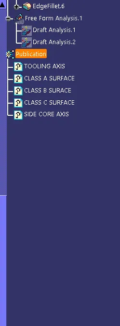
REFERENCE FOR CLASS A, CLASS B & CLASS C SURFACE.
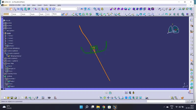
CLASS A SURFACE
check the surface quality
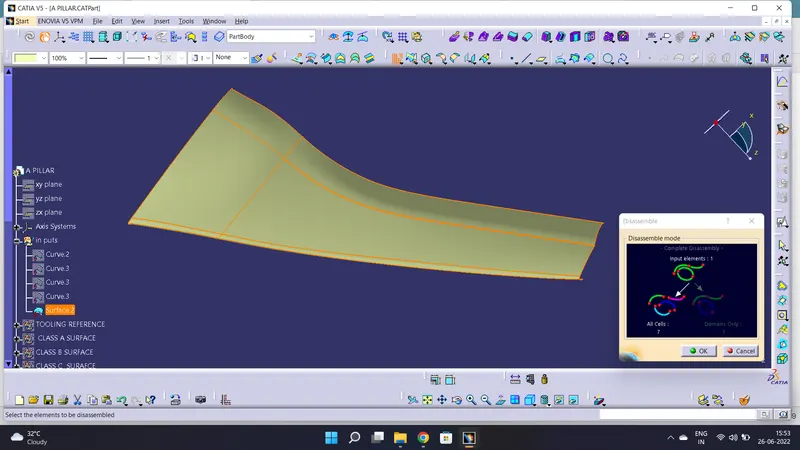
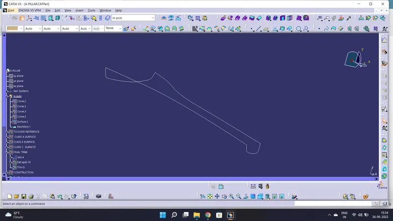
check the any patches available in surface with boundary
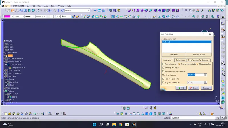
let's join the surface
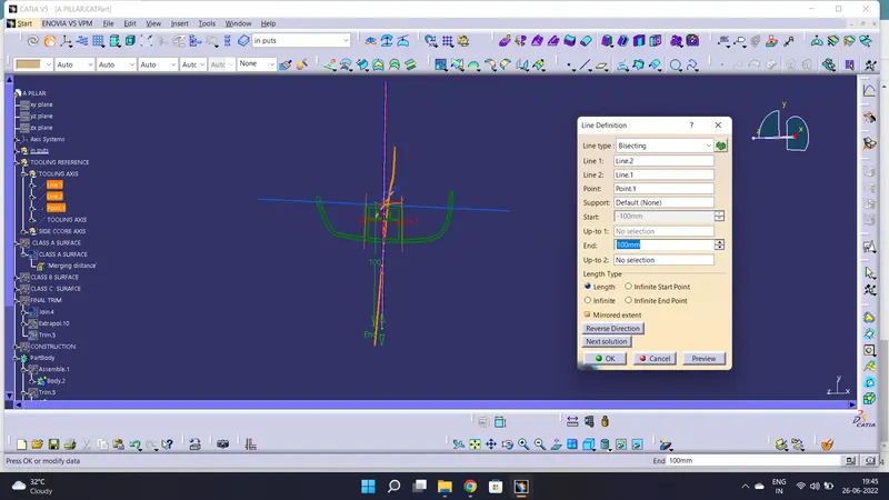
TOOLING AXIS
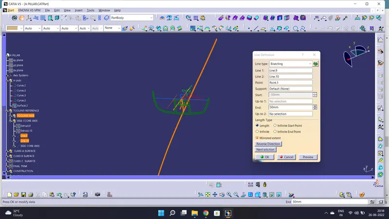
create the two lines with the master section, bisecting the line & create the tooling axis.
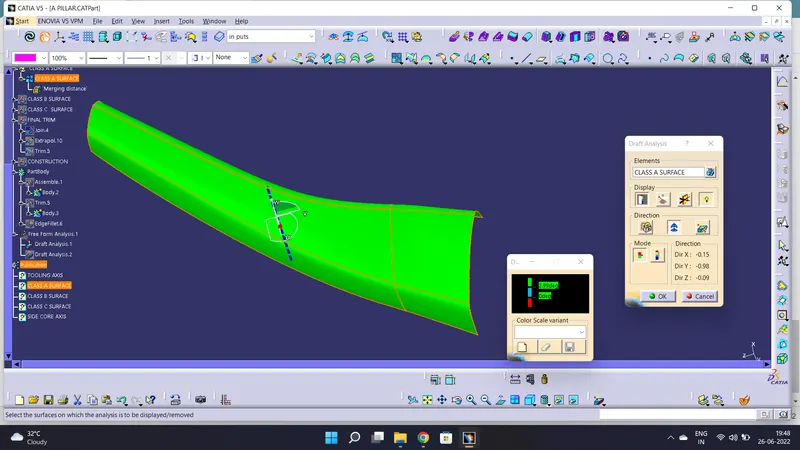
DRAFT ANALAYSIS
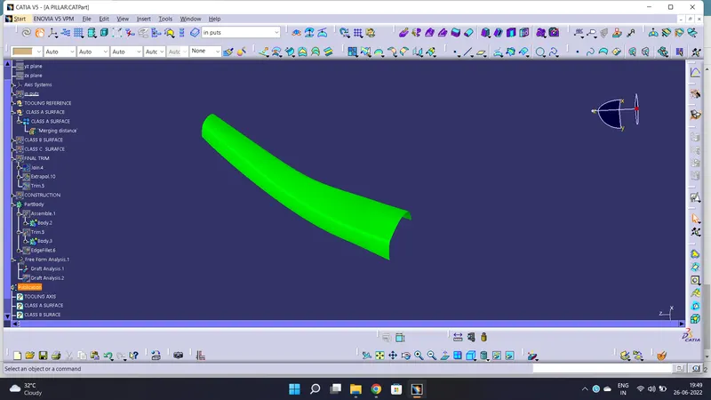
Draft analysis for class A surface
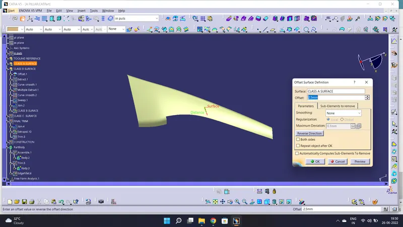
CLASS B SURFACE
Create B surface offset form the class A surface as per master section.
missing surfaces create with swept surface.
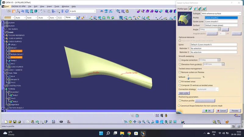
let's join the surfaces & create the class B surface.
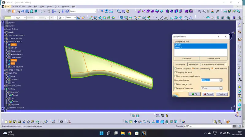
CLASS C SURFACE
create the surface with swept & multi section surfaces.
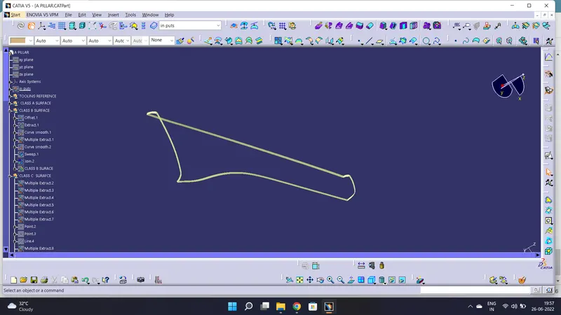
FINAL SURFACE
Join the surfaces without any boundary.
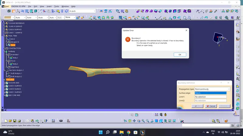

SIDE CORE AXIS
create side core axis using master section.
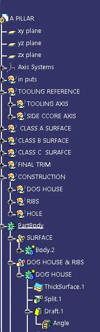
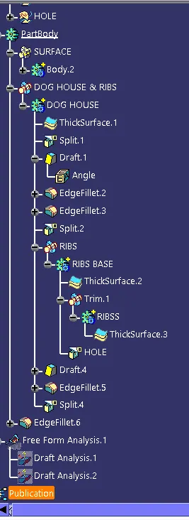
DOG HOUSE & RIBS
Create the dog house & ribs as per master section.
DOG HOUSE
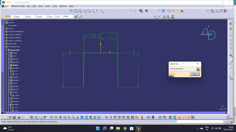
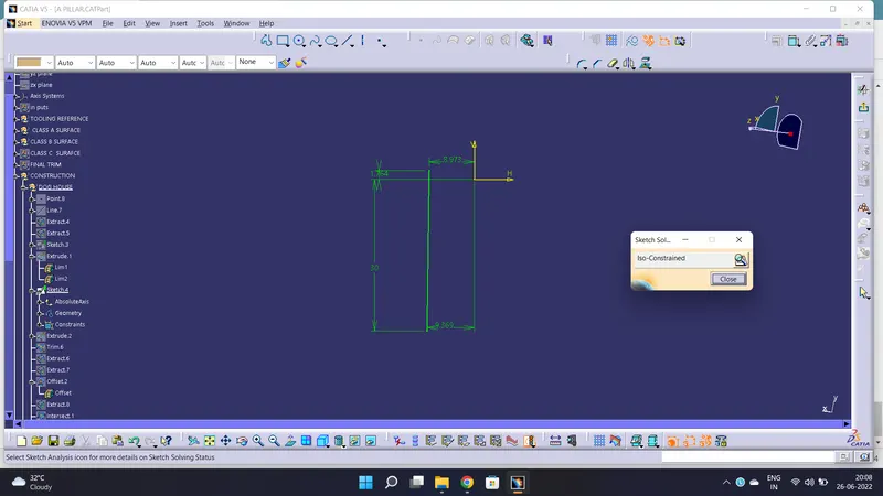
Extrude the sketch convert to sloid.
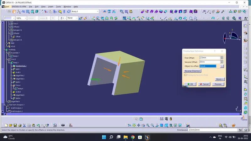
to reduce the sink marks.
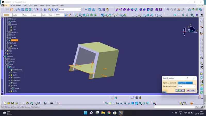
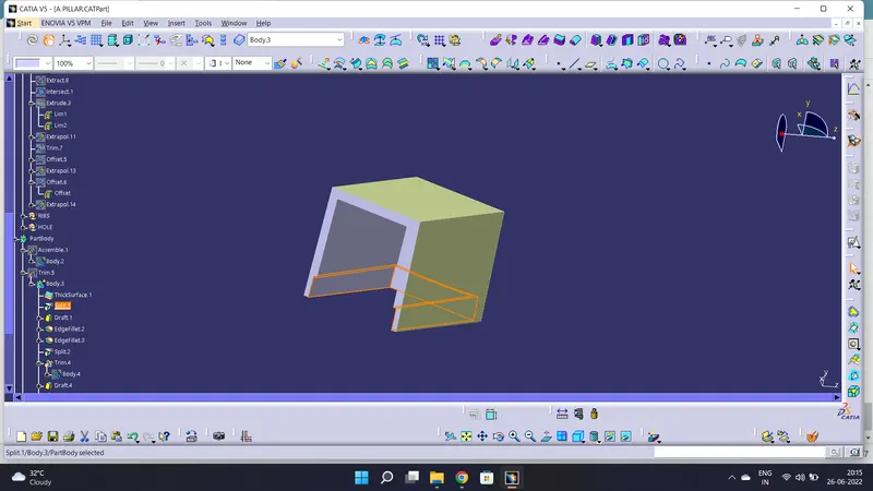
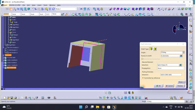
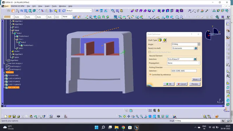
draft to the dog house using side core axis.
RIBS
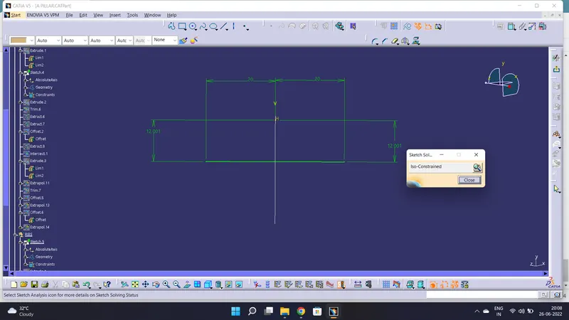
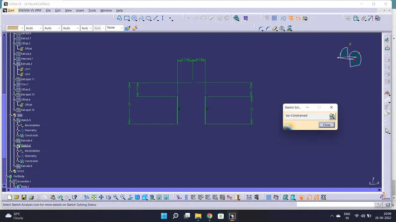
Extrude the sketch convert to sloid.
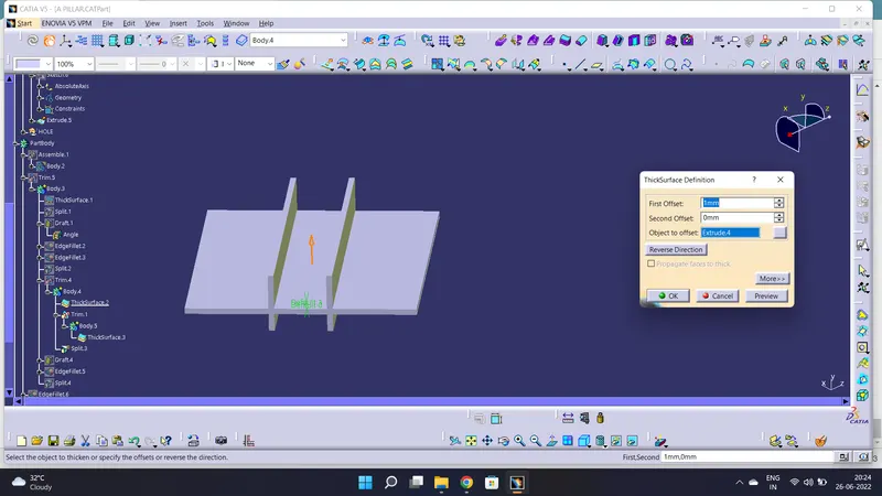
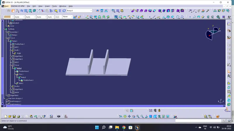
DRAFT TO RIBS USING SIDE CORE AXIS
DOG HOUSE TOP PROFILE
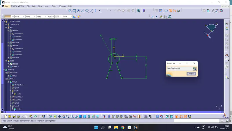
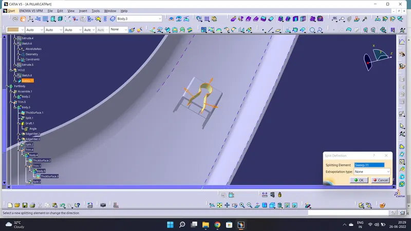
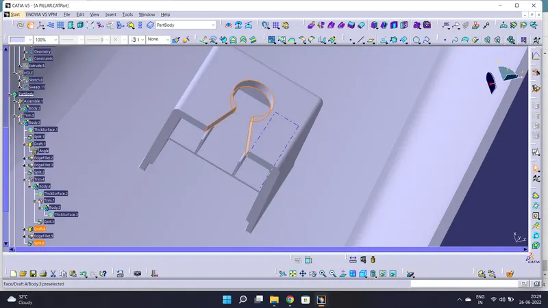
GIVEN FILLETS TO THE DOG HOUSE & RIBS AS PER MASTER SECTION.
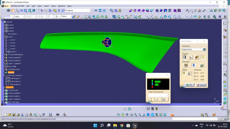
DRAFT ANALYSIS FOR SOLID SURFACE
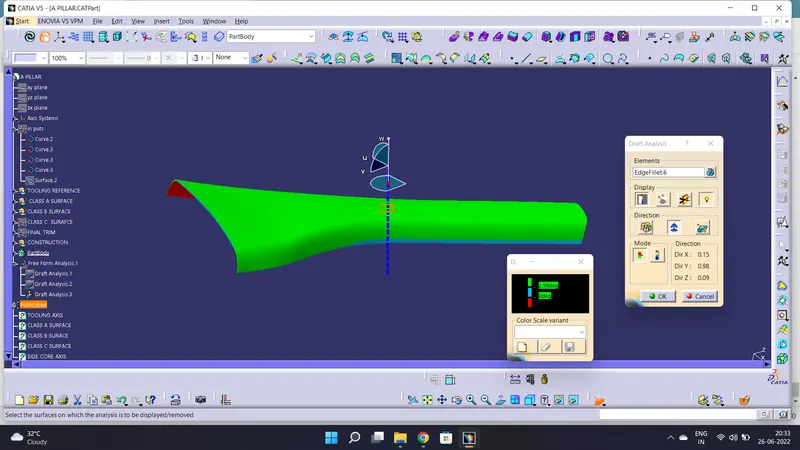
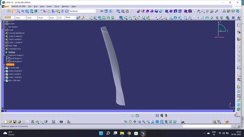
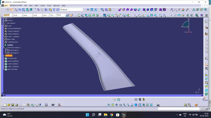
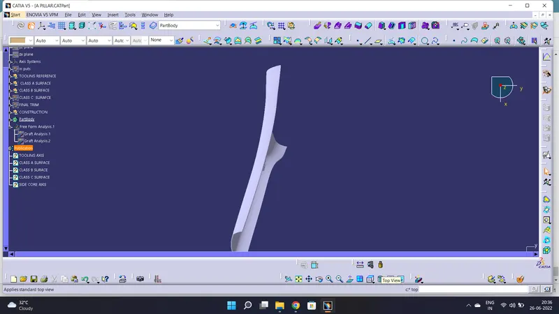
VIEWS