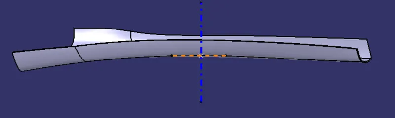
Week 9 - Project - A pillar Design with Master Section
Report -
A PILLAR: A-Pillars straddle the windshield, B-Pillars are in the middle of the passenger compartment (just behind the front doors) and C-Pillars are those at the rear of the passenger compartment.

MASTER SECTION: Master sections are the guides for design requirements which decide the component packaging after technical (Styling, Concept or Class-A) surfaces. Creating this master section should need 5 to 6 years of experience. This helps you to decide the feasibility, clearance, the packaging and the fixation strategy before working it on a 3D.
Draft analysis of given plastic component -
Draft analysis is important here to check the feasibility of manufacturing the component. A safe draft angle of 3 degrees is provided so that the surface of the component upon shrinking does not stick to the core surface. Upon cooling within few seconds, it is the tendency of the plastic moulded component to shrink towards the core surface. This can cause diffculty to remove the final component or can even damage the surface of the component and core.
Creation of tooling axis -
There are generally four methods of creating tooling axis to check whether the component will clear the draft analysis test.
1. Along axis direction (X,Y,Z)
2. Normal to face part
3. Trial and error compass
4. Bisecting line method
- Bisecting method is used here for creation of main tooling axis.
- Given data in the form of master section is leveraged to create tooling axis.
- Attachment feature dog house is given a required draft angle with respet to the main tooling axis.
- Hence, Dog house is used to create main tooling axis.
- Two sides are used to create a bisecting line. Rear side and front face is used to create another bisecting line. A new bisecting line using the two bisecting lines is created.
- This is the main tooling axis
- Lifter axis is created perpendicular to the main tooling axis.
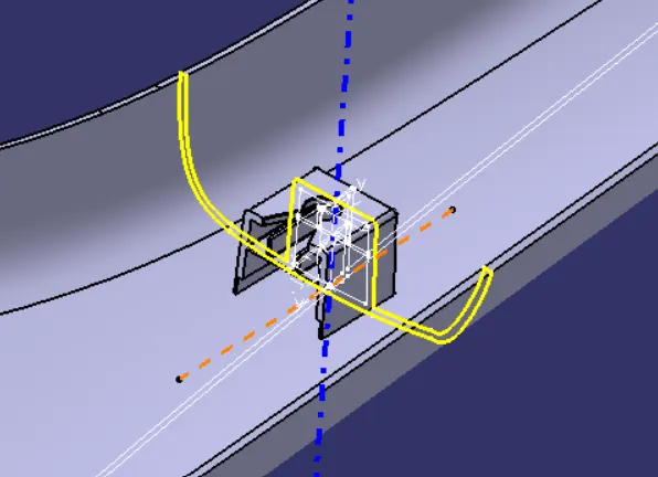
Fig - Main tooling axis and Lifter axis from Master section
Design Rules for Dog house -
- Dog house wall thickness at intersection of part wall (C) should be less than 40% or less than the main wall stock.
- Height 0f (B) should be between 3.0 mm to 6.0 mm
- Minimum dog house width is 12 mm
- Minimum dog house draft is 1.5 degree to draw the die. If a slide is being considered this minimum requirement can change to 3 degrees.
- Inside walls are given a draft angle of 0.5 degrees minimum.
Here are the images of draft analysis done of Class A surface and the final solid component -
Class A surface -
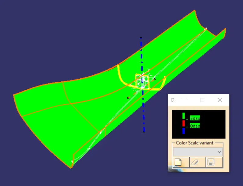
The whole A surface is clearing the draft angle requirement of 3 degrees. The draft angle is given with respect to the main tooling direction.
Part body -
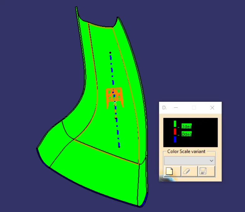
The closed body is clearing the draft angle requirement of 3 degrees with respect to the main tooling axis.
Dog House -
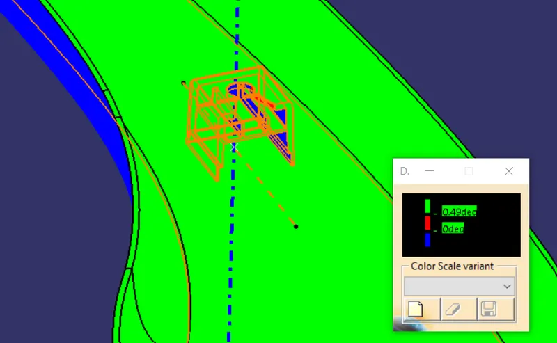
The outer surfaces of the Dog house are clearing the draft nagle requirement of 1.5 degrees with respect to the main tooling direction.
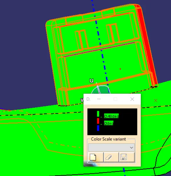
The inner walls of dog house are clearing the minimum draft angle requirement of 0.5 degrees with respect to the lifter axis which is perpendicular to the main tooling axis.
Isometric view -
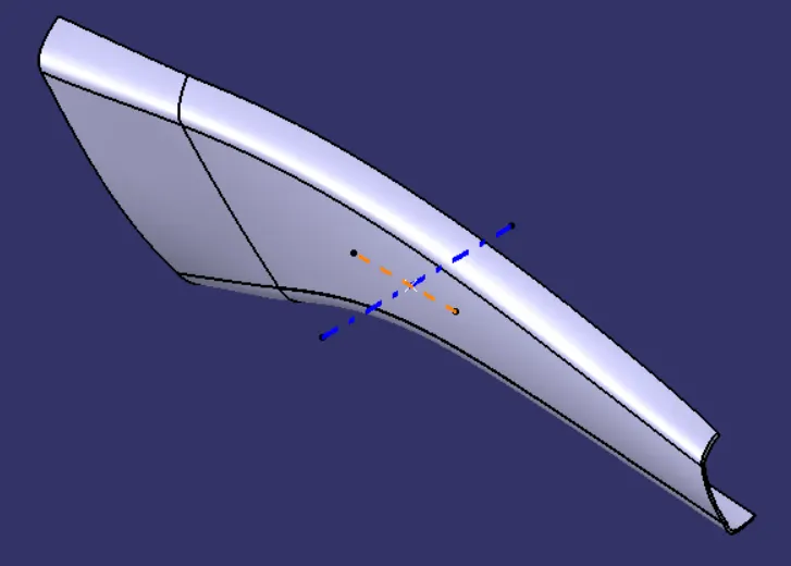
Front view -
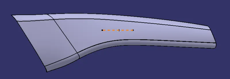
Side view -
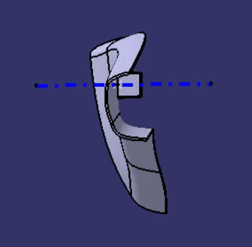
Top view -