Week 9 - Project - A pillar Design with Master Section
A pillar Design with Master Section
Objective of the Project:
Create A Pillar plastic component with the help of Master Section and check whether it is feasible to manufacture or not. Also, perform draft analysis for Class A surface and final component with Dog House.
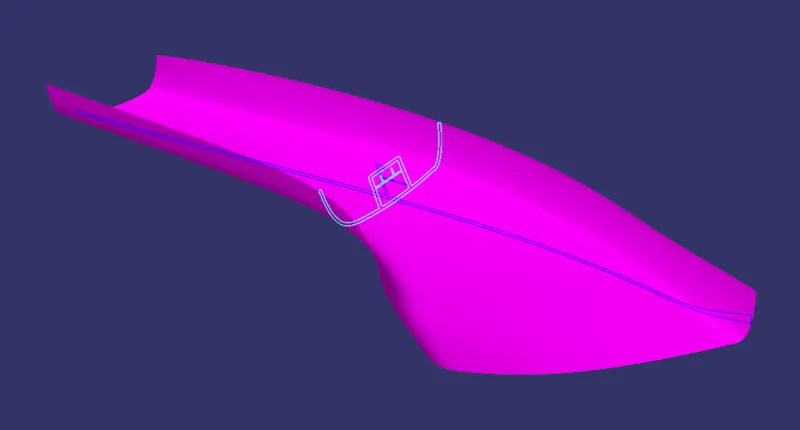
Given Class A Surface with Master Section:
To design the A Pillar first we need Class A Surface, if we have Class A Surface means we can create the tooling axis and do further design.

Class A Surface With Master Section:
Master Section:
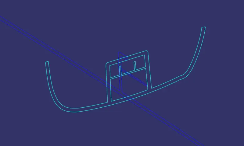
We are going to create the tooling axis by considering the Master Section. We can decide the thickness of the component by mesuring the thickness of the Master Section.
The thickness of the component is 2.5mm.
Tooling Axis:
Tooling axis is very important to design a product. It is nothing but the direction of the molds open close and whether it is moves in the x, y or z direction. First we have to decide which direction is probabily suitable for the particular product. Once we get the Cass A Surface, we can check the surface and able to create the tooling direction.
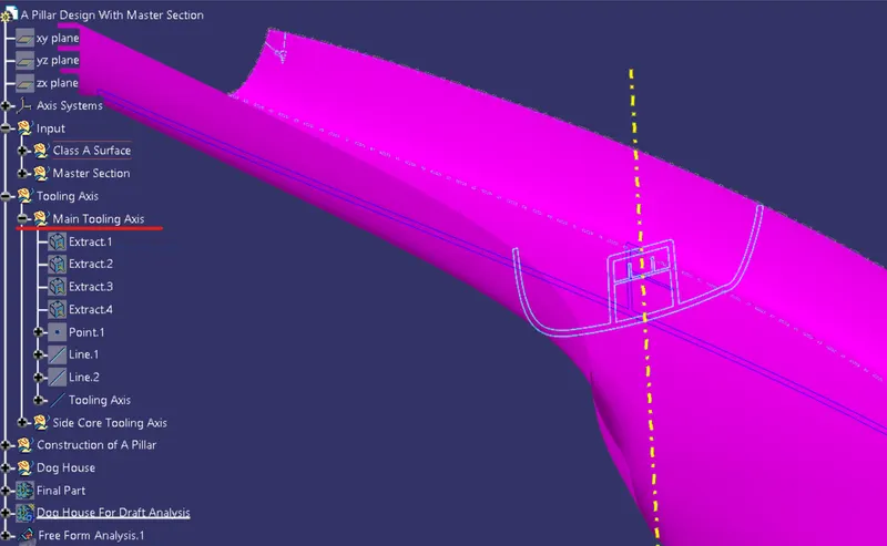
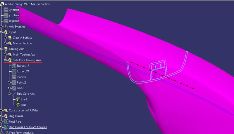
Here we have to create two tooling axis one is for final product (Mian Tooling Axis) another for Dog house(Side core Tooling Axis).
1.Main Tooling Axis:
Procedure to Create the Tooling Axis:
- First, we have to create a point between the master section of Dog House by taking two points.
- Once we created the point, we can create a line on the point by using bisecting line with the help of extracted line from the dog house master section. and do the same process in other master section dog house.
- We can find the suitable direction by simply see the object from x,y and z directions. If the object is fully visible from one of the direction means that is the line direction.
- After creating the two line which might create a problem, then draw a biseting line using the two bisecting line that we drawn from the master section of dog house.Here we used Bisecting Method to create the Tooloing axis.
- Here, the tree structure shows the steps followed to create the tooling axis.
2.Side Core Tooling Axis:
Here also we are using the same procedure that we used to create the main tooling axis but insted of creating vertical bisecting line we are creating horizontal line that sholud be perpendicular to the main tooling axis.
Drfat Analysis:
Draft: Draft is used to remove the component fom the core and cavity. It will reduce the wear in component and molds so the the life of core and cavity will increase.
Draft Analysis: The Draft Analysis allows the user to easily analyze a part for proper draft angle. A Draft Angle describes the amount of taper for molded or cast parts perpendicular to the parting line.
The minimum draft angle ranges between 0.5 o 3 degree. Mostly 3 degree angle is widly used to make many components.
Class A Draft Analysis:
Procedure to do Draft Analysis:
- Once we created the tooling axis means we can do draft analysis. First we have to switch the view mode to shading with material.
- After switching to shading with material mode we can now click draft analysis tool. Then we have to place the compass on the tooling axis by clicking and draging the compass red dot.
- After placing the compass lock the direction and click the surface to do draft analysis.
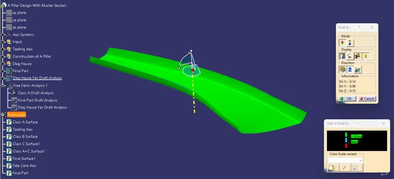
- From the above image we can see that the green area has the draft angle above 2.9 degree.
- Here there is no blue or red color in the surface if there is any blue color surface means the draft angle ranges between 0 to 3 degree.
- If the color is red means negative or below 0 degree.
- We can change the color and angle value by clicking the color and values. But green,blue,red are standard colors.
Final Plastic Component With Dog House Draft Analysis:
Here also we are using the same methods that we followed in class A draft analysis but instead of class A surface we are choosing Final Plastic Component with Dog House(Closed Part).
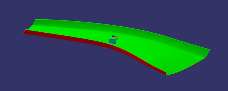
- From the above image we can see that the plastic component is clearing the darft analysis so that it is possible to manufacture this part.
- The green area has more than 2.9 degree angle so it is possible to eject the component from the mold without sticking to mold.
- We can see a blue color area on the dog house faces that means the draft angle ranges between 0.45 to 2.9 degree but the actual degree is 2.5 degree we can check the individual spot degree by using analysis under the running point tool in the display of the draft tool.
- In other blue color areas the draft angle is 0.5mm.
Dog House Draft Analysis Using Side Core Tooling Axis:
Here also we are using the same methods that we followed in class A and final component draft analysis but instead of selecting the Main tooling axis we have tio select Side Core Tooling Axis.
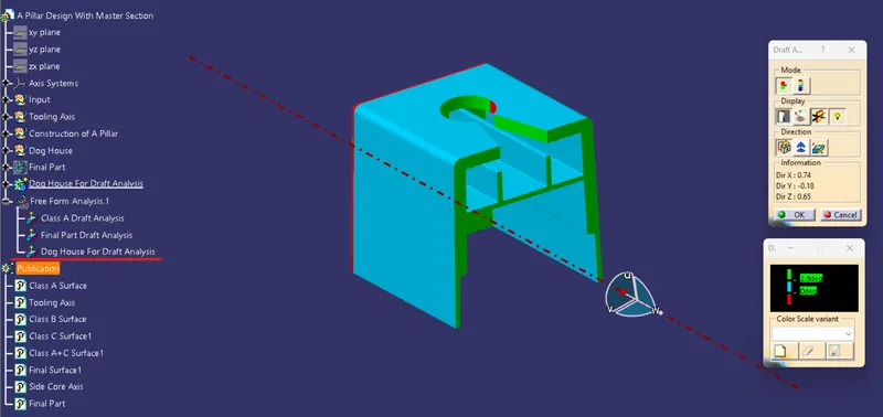
- From the above image we can see that the Dog House clearing the darft analysis so that it is possible to manufacture this part.
- The green area has more than 2.9 degree angle so it is possible to eject the component from the mold without sticking to mold.
- We can see a blue color area on the dog house inside faces that means the draft angle ranges between 0 to 2.9 degree but the actual degree is 2.5 degree we can check the individual spot degree by using analysis under the running point tool in the display of the draft tool.
- We don't want to consider the outside area because it already clearing the draft analysis with main tooling axis.
Class B Surface Creation:
Class B Surface is the inner surface it can be created by using the class A surface by using several surface features.
Basic Features used in Class B Creation:
- Offset
- Extract
- Trim
- Extrapolate
- Radius
- Sweep
- Join
- Multisection
- Extrude etc.,
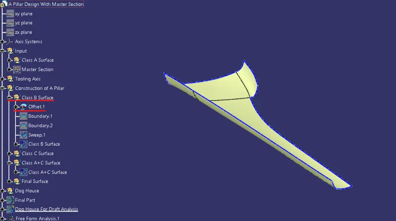
The above image shows that the direct offset from Class A Surface and it has some unfilled areas, we have to correct that.
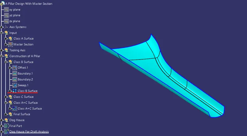
The above images shows the process of creating the class B surface from class A Surface.
Class C Surface Creation:
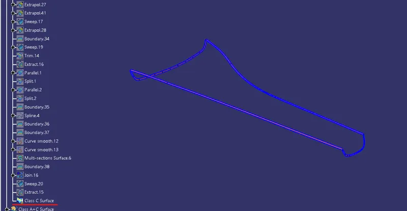
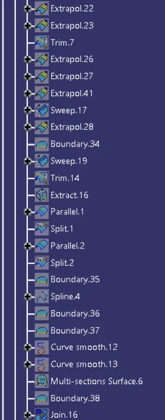
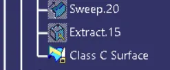
The surface which is used to close the class A and clas B surface is called class C surface. Simply it gives thickness to the component. We can create the surface using the features mentioned in the below image or other features.
Here, we can create the C surface using sweep with reference surface and sweep with draft direction also we can using multisection for twisted corners.
Class A+C Surface:
After the creation of the class C surface we can join both of the class A and class C surface with join command.
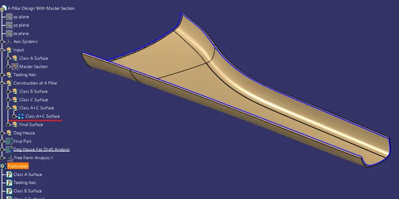
Final Surface Creation:
After the joining of class A and B surfaces we can trim it with class B surface which we created.
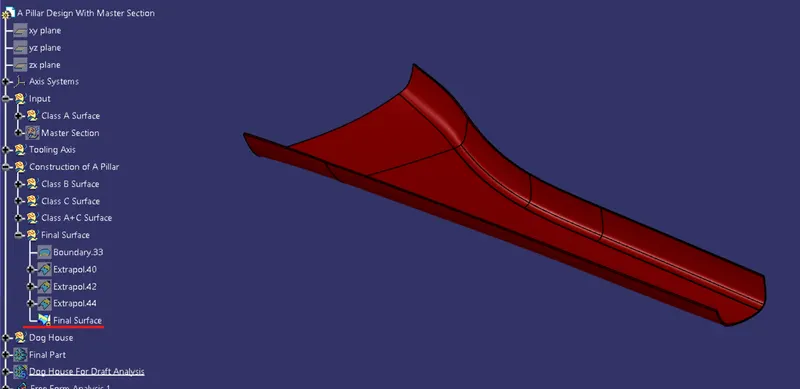
- After the creation of Final(A+B+C) surface we have to ensure that the wholesurface is closed or not by using boundary command if it shows error then the surface is closed.
Solid Plastic Component With Dog House:
We created only surfaces but we need solid part so after the creation of all surfaces we should do close surface from part workbench. Finally the A Pillar with Dog House Design is ready for manufacturing.
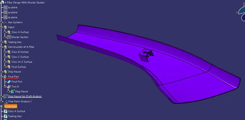
Dog House Creation:
Dog house is an engineering feature used in plastic trim design. Dog houses are used as supporting feature. Sometimes other engineering features like snaps; locators etc. are mounded on them to increase their strength.
Here, the Dog House is created by using the given master section.
Dog House Design Roles:
- Take the Thickness of the component to be 2.5 mm
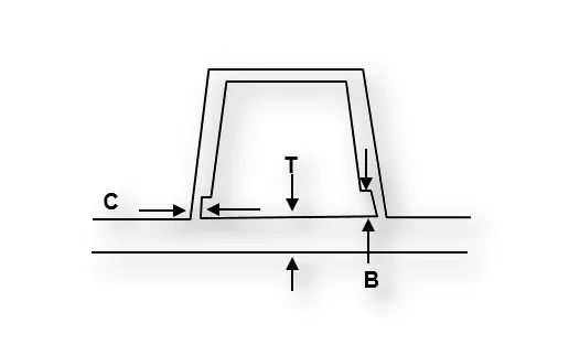
- "C" is where the doghouse contacts the backside of the surface.
-
Doghouse wall thickness at the intersection of the part wall ( C ) should be 40% or less than the main wall stock ( T ).
-
The height of ( B ) should be between 3.0 – 6.0 mm
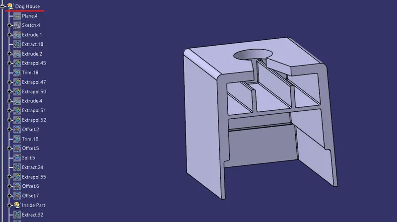
Here thicksurface, split, edgefillets are used to create the Dog house.
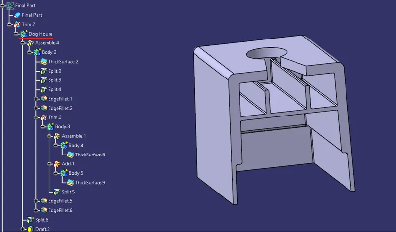
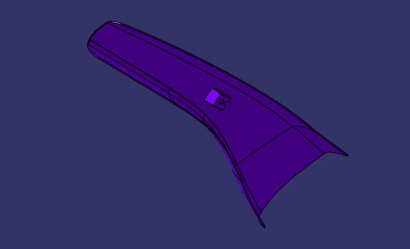
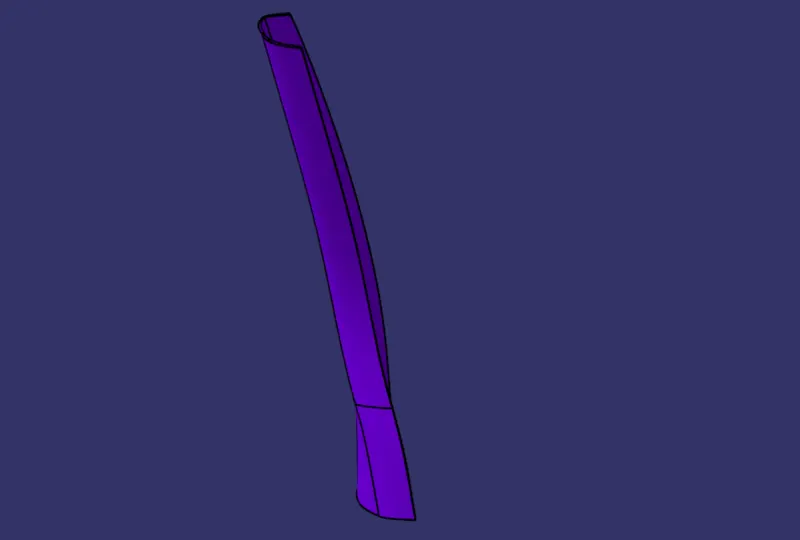
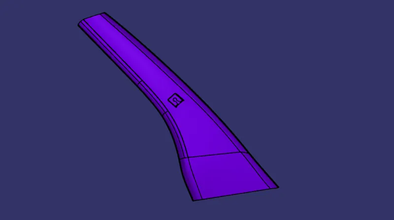
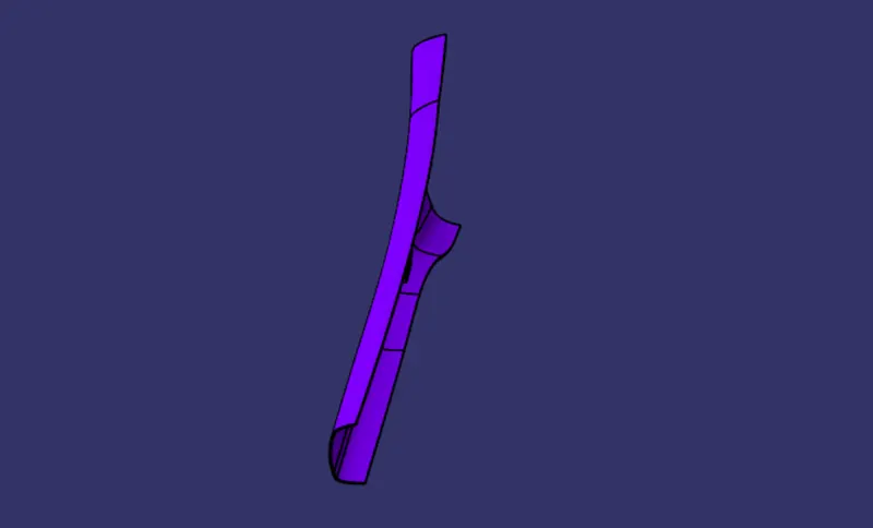
Completed design in various orientations (Isometric, Front, Side, and Top View):
Conclusion:
The creation of A Pillar with Master Section is completed and the draft analysis performed on the final plastic component.