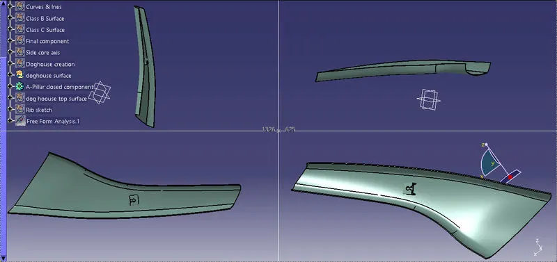
Week 9 - Project - A pillar Design with Master Section
AIM:
To creat DOG HOSE & RIB for a gven CATPART Class A Syrface to make Class B &C Surface Attach with Engineering features for A -PILLAR PLASTIC Component.
Used via
Catia V5 software- tools used given below,
- Point through on the centre of surafce
- Axis creation
- Line in point direction
- Bisectecting line
- Intersection
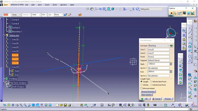
- Tool Axis
- Draft Analysis in Free from Analysis
- Untrim
- boundry
- extract boundry
- multiple extract boundry
- Extraploate
- Offset
- Trim
- Join
- Sweep command purticularly withreference surface
- blend
- fill surface
- Extruded surface
- multisection surface
- Fillet
- Closed Surface
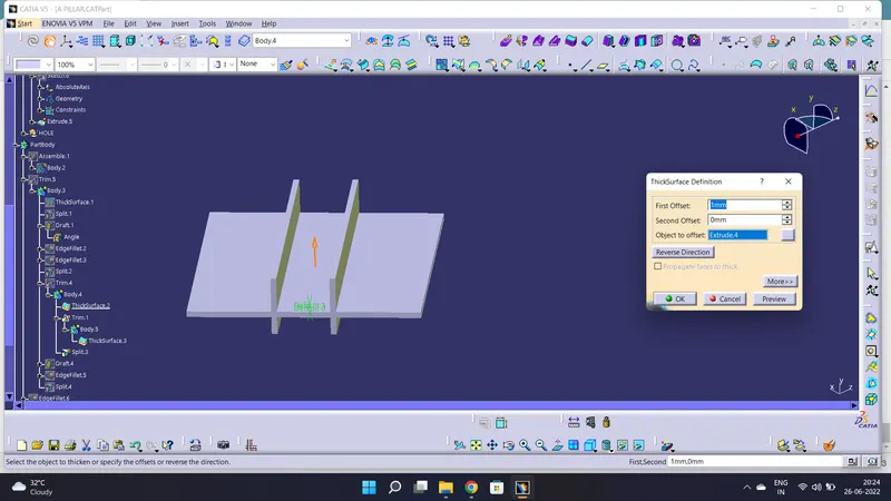
- Thicken surface
- Pad
- Draft
- Fillet
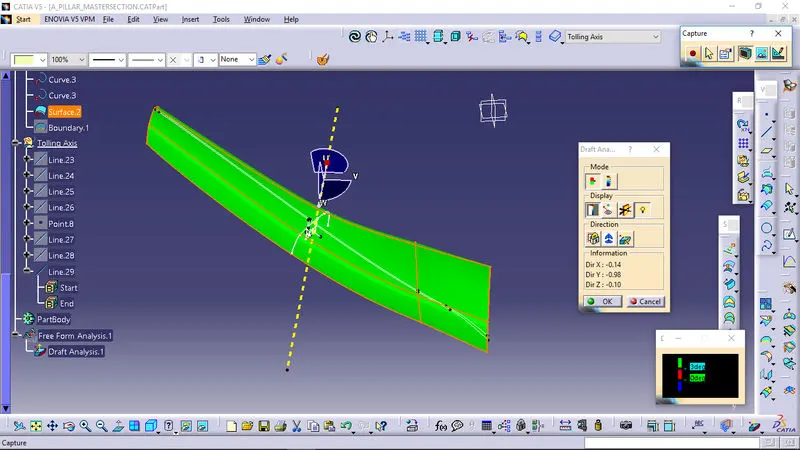
TOOLING AXIS :
The tool axis is the parameter which decides whether the tool enters into mould or not as as it denotes the draft clearance angle where a moulded part is easily removed from the mould.Component should be 2.5 mm thickness.
-
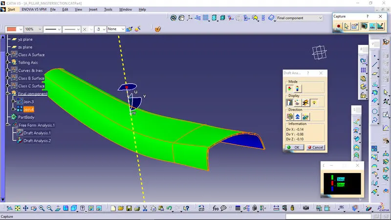
DRAFT ANALYSIS :
- No parts can be ejected from the tool if it is having a straight 90 degree profile from its base surface. A small draft angle is provided to each and every area of the component in order to get an easy removal of the component from the tool.
- Draft analysis technique is used to analyze whether our part model created in cad is manufacturable based on the draft condition applied. Here the part should get easily removed from the panel dies (in case of Sheet metal part) or Mold (in case of plastic).
- Here we are providing a direction in which components should eject inorder to get an easy removal of components from the tool. In other words it also lets us know whether the model is having a draft angle and how much is the draft angle from the tool direction.
-
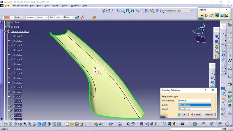
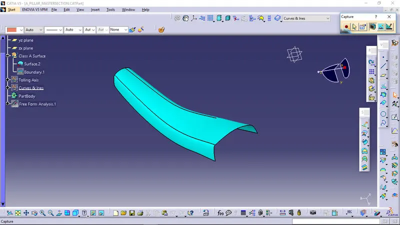
SURFACE-A:
TOOLING AXIS:
DRAFT ANALYSIS A-SURFACE & FINAL COMPONENT:
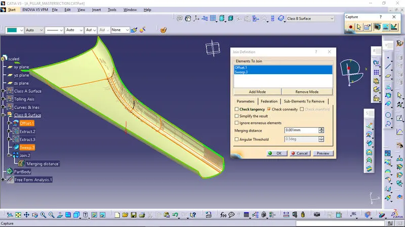
B-SURFAC:
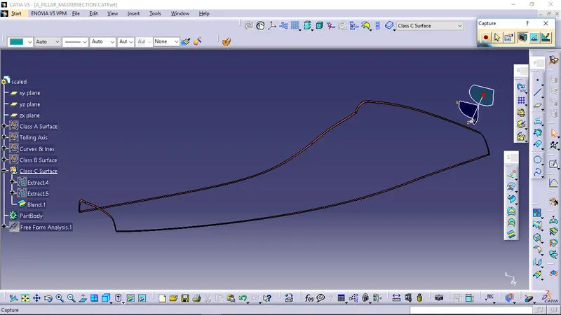
SURFACE -C:
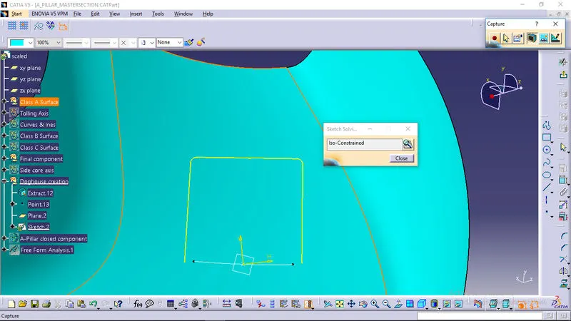
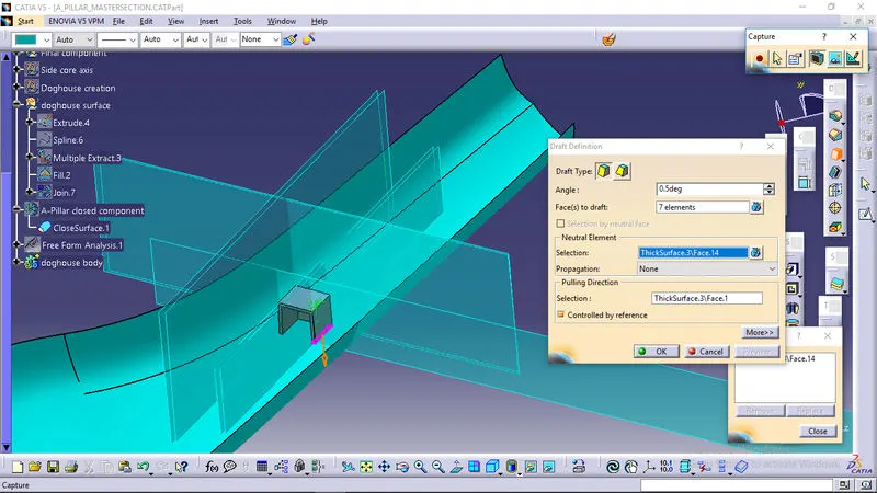
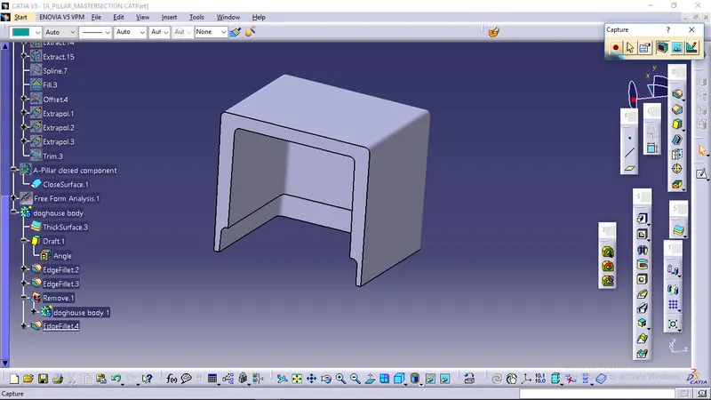
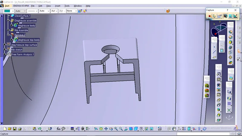
DOG HOUS:
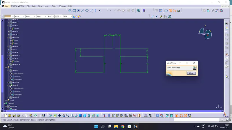
RIB:
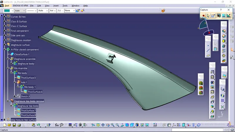
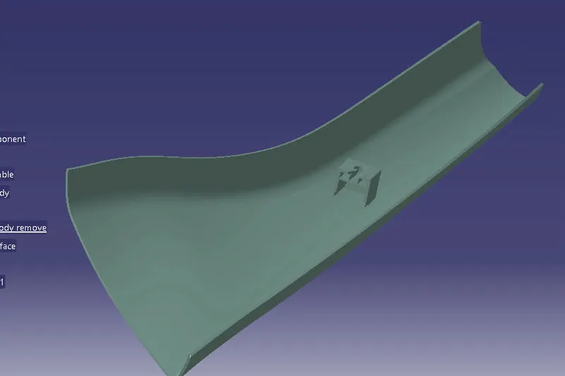
FINAL BODY:
ORIENTATION: