Week 9 - Project - A pillar Design with Master Section
Aim
- To create the class B and class C surfaces from the given class A surface
- To form a solid geometry by combining all the surfaces
- To create a dog house for the solid part whilst following the design rules
- To perform draft analysis on the class A surface and the solid part model
A-PILLAR
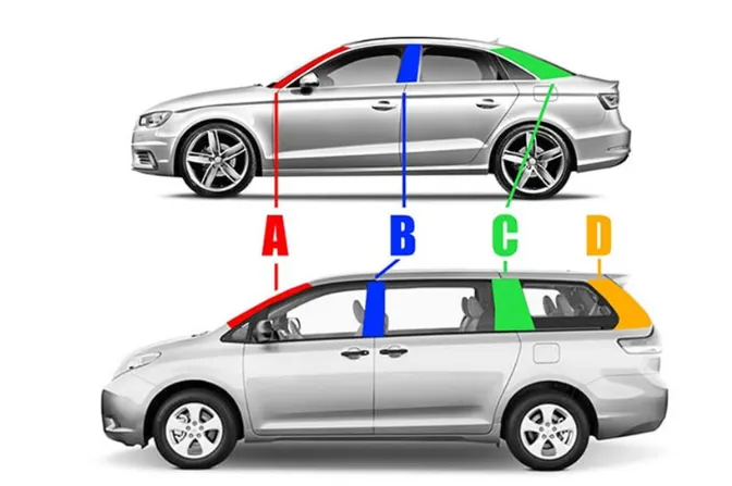
The structure of an automobile body consists of various support structures like the roof, pillars, and floor. The car pillar in the vehicle stands in the near-vertical position, which supports the vehicle’s roof. The pillars found most commonly are the A, B, C and D pillars.
The A pillars are the first set of upright sections on a car body that links the lower body to the roof of the car. It acts as a major support structure during impacts and it is also a median to support the windshield of the vehicle. Apart from structural advantages the A pillar has a large effect on the overall aerodynamics of the vehicle.
INTRODUCTION:
CLASS-A SURFACE: A surface made by the designer which is given as an input to the plastic modeler/ sheet metal designer to work on. It is aesthetic surface and the outer most surface.
CLASS-B SURFACE: A surface below a certain thickness from the class-A surface is class-B surface. This is the surface that contains engineering aspects of a model for example Ribs cutout.
CLASS-C SURFACE: A surface that joins class-A and class-B surfaces together is called as a class-C surface.
Draft Analysis:- Draft is a taper applied to the faces of the part that prevent them from being parallel to the motion of the mold opening. This keeps the part from being damaged due to the scraping as the part is ejected out of the mold, to do that the analysis is done and known as Draft Analysis
Tooling axis: The direction in which the mold or core and cavity opens is called as the tooling axis.
MASTER SECTION:
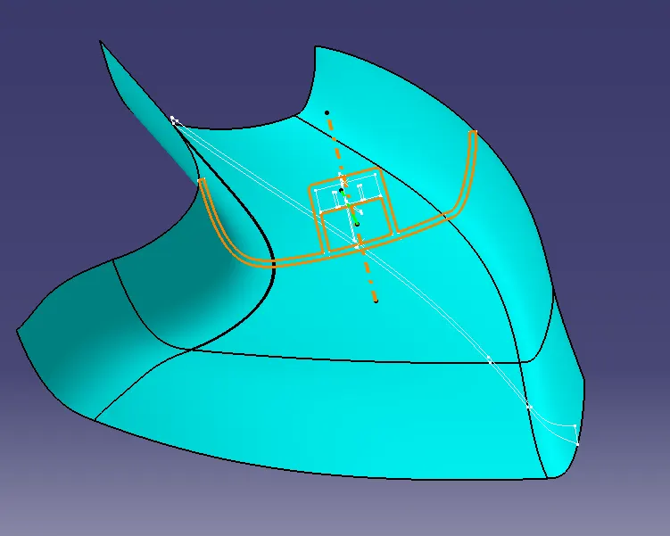
Master sections are the guides for design requirements which decide the component packaging after the styling surface
PRE-DESIGN CHECKS:
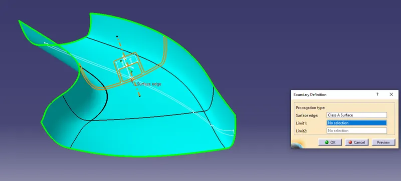
Before starting the creation of the class B surface we must ensure that the given class A surface is properly closed and the surface continuity is proper. This can be done either with the help of the join operation or by using the boundary feature.
TOOLING AXIS:
- The next step is to create the tooling axis for the part which will determine the direction in which the core and cavity of the mould will move.
- Designer must ensure that all holes and slots are covered in the main tooling and thus side core must be avoided whenever possible
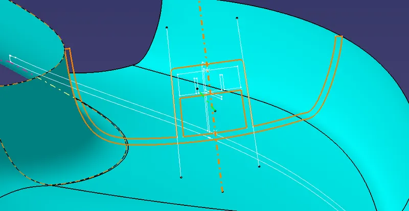
- After analysing visually for the best possible tooling axis, an reference tooling axis is created on the centre of one of the surfaces of the A pillar trim.
- The main tooling axis is created by using the bisecting method and by taking references from the master section
DRAFT ANALYSIS:
- Draft analysis is done on the class a surface after the tooling axis has been obtained
- The part must have a minimum draft angle of 3 degrees on all the tapered faces
- Using the feature draft analysis tool and the compass the part surface is validated for the minimum draft criteria
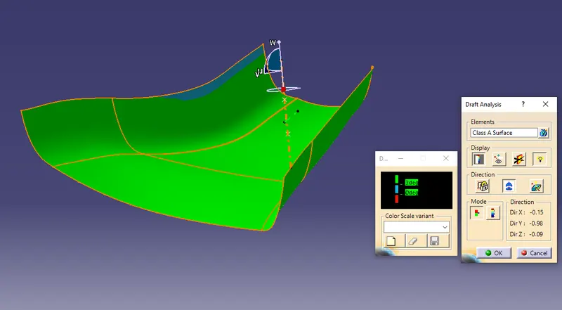
Due to Class A surface irregularity there are some areas which are blue to rectify this the Class A team need to be informed and coordinated in order to get the surface fixed
CLASS B SURFACE
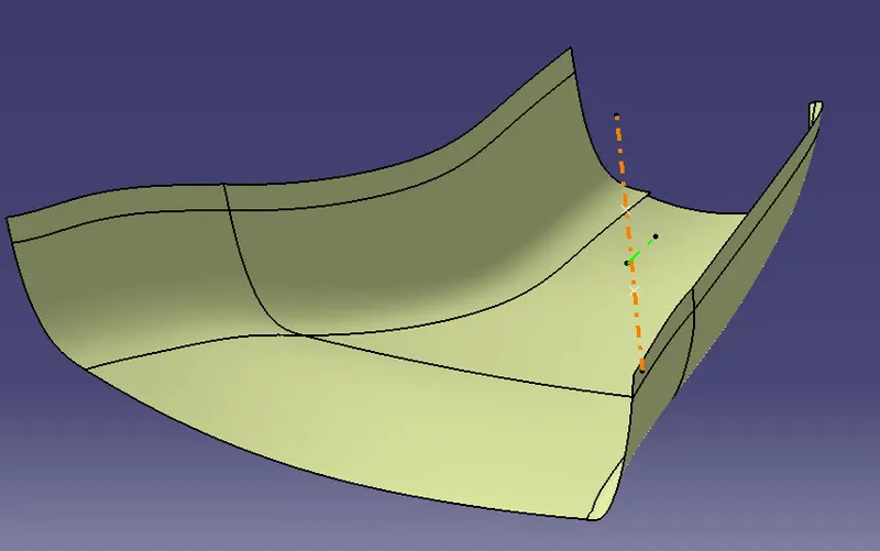
- After all the validation has been done, the class B surface is created by offsetting the class B surface to a distance of 2.5 mm
- After offsetting a large opening in the surfaces is found which is closed with the help of sweep and multi section commands
- The class B surface is then extrapolated in parts to trim it along with the class C surface
CLASS C SURFACE
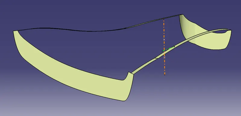
- The class C surface which connects the class A and class B surface is created by sweeping the boundary of the class A and using the class A as a reference.
- The sweep is divided into several parts in order to avoid complexity
- Surfaces which are parallel to the tooling direction are swept with the tooling axis as reference and with a draft angle of 3degrees
Final Trims:
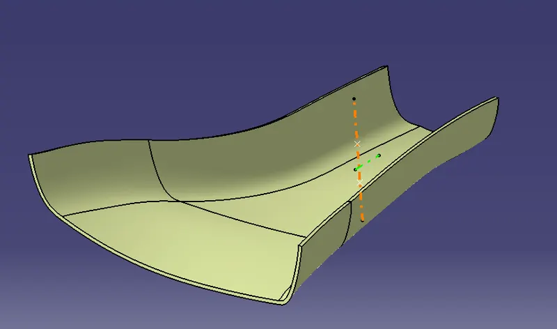
Class A + Class C:
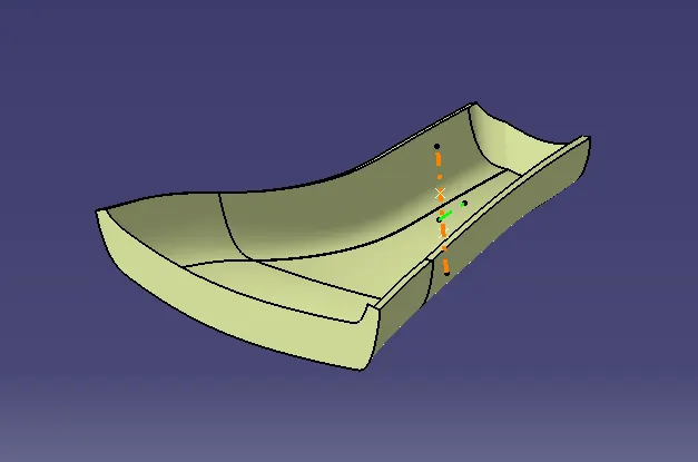
Then both class A and class C surface are joined to get the surface which is going to be trimmed off with class B surface in order to get the closed surface
Class A + Class B + Class C:
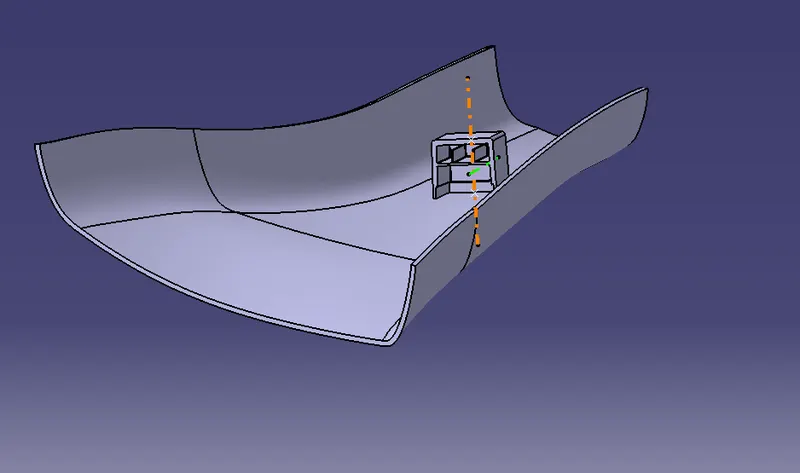
After trimming we get the closed surface and then we go to part design and use closed surace to create the plastic part
B Side Features Creation
Dog House Creation
Design Priincipals for Dog House Creation
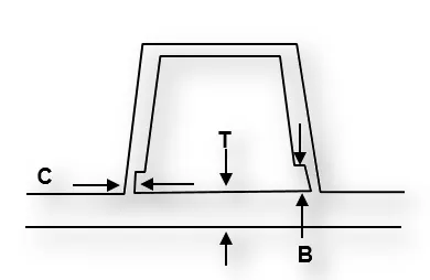
"C" is where the doghouse contacts the backside of the surface
-
Doghouse wall thickness at the intersection of the part wall ( C ) should be 40% or less than the main wall stock ( T ).
-
The height of ( B ) should be between 3.0 – 6.0 mm
The Surfaces That Are Cleared Along The Lifter Axis Are Also Given a Minumal Draft
-The Height Of The Attahcment Walls Should Be a Minimum Of 3 Mm
-This Avoids The Plastic Defects On The B Side And Maintains The Texture Of A Side
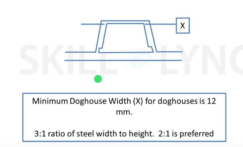
Procedure for creating the dog house
- First extract a face and create a rectangle and extrude it (Give direction as tooling Axis) and with shell command remove the face with a thickness of 2 mm.
- Give the draft of 1.5 degree on outer walls with the pulling direction as tooling axis (make sure you cut the material).
- For inside faces make a tooling axis (Side Core) by following the same method and then give a draft of 0.5 inside (make sure you cut the material) and then extract the inner face.
- Extract the bottom surface and give a offset of 3-6mm and trime with the side wall and then extrapolate the trim and then split the surface with the solid and then take an draft analysis and after that provide draft to the faces which didnt have draft and provide the required fillets.
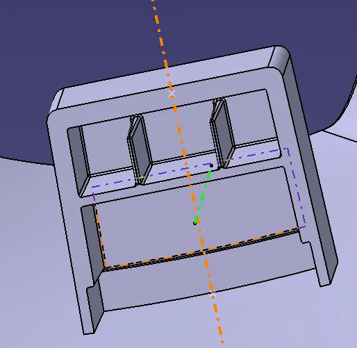
Draft Analysis of the final part with Dog House and the Dog House (Engineering Features)
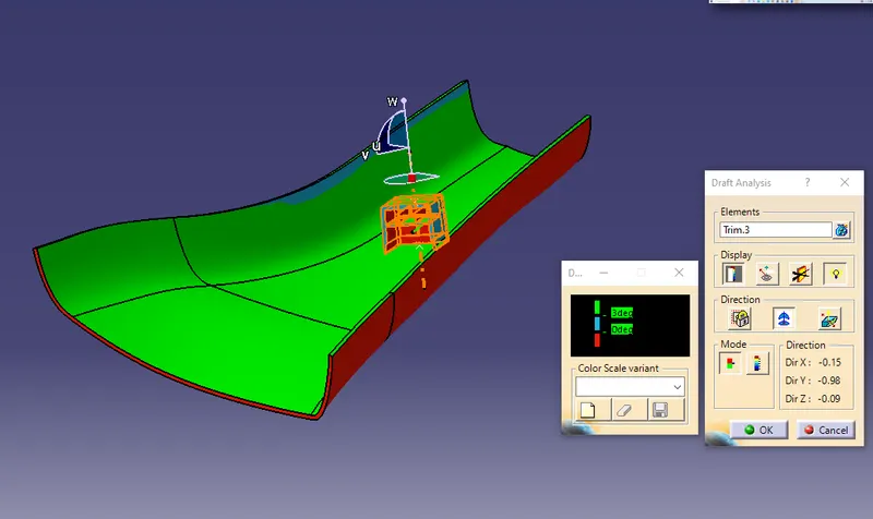
Draft analysis with tooling direction at 1.45 deg it is passing the analysis
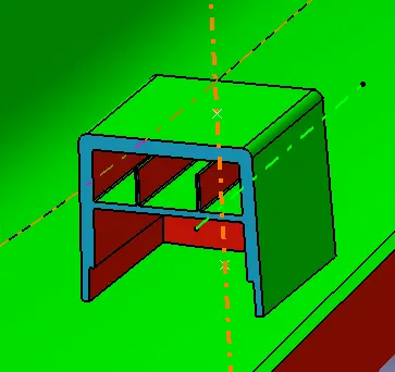
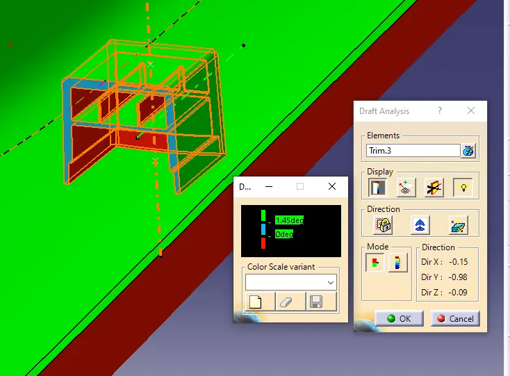
Draft analysis with Side core tooling direction at 0.45 deg it is passing the analysis
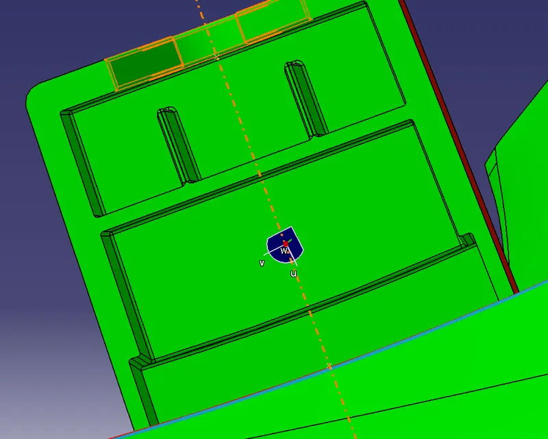
Draft Analysis of Final Part with Dog House
The Door Trim is passing the draft analysis and at some places there are irregularities in the class A surface thats why it is showing the red and blue.
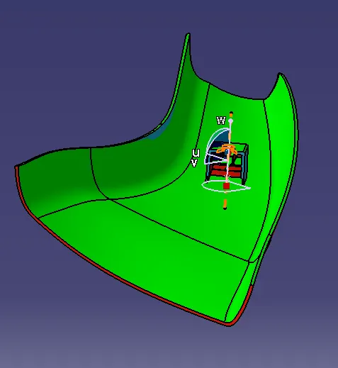
Please find the attached part for your review