Week 9 - Project - A pillar Design with Master Section
AIM:
To create the A pillar with master section plastic component through the given class A surface. To begin with the tooling axis for the given class A surface should be created meeting the requirements of the draft angle and at the end perform the draft analysis for for the closed solid model of the A pillar . Take the thickness of the model to be 2.5mm.
OBJECTIVE:
- Creating the tooling axis for the given class A surface.
- Perform the draft analysis to given class A surface with the tooling axis.
- Creating the class B with the offset distance of 2.5mm.
- Creating the class C surface.
- Then join the class A & class B & class C surface and make as closed solid.
- Atlast perform the draft analysis to the closed solid.
DESING METHODOLOGY FOR MAKING CLASS A SURFACE INTO CLOSED SOLID MODEL:
CREATING TOOLING AXIS
- The axis in which the moment of core and cavity are take place is known as the tooling axis.
- There are three method to create the tooling axis.
- Any one of the standard axis as Tooling axis.
- Creating line Normal to the any one of the surface in the model as tooling axis.
- Creating bisecting line on model and make as tooling axis.
- In this model we use the second method to creating tooling axis.
Creating line normal to the any one of the surface.
- Extact the flat surface of the model to create the point and line.
- Create the point on the extract surface which we want to make a normal line to the surface.
- Then create the line with using the normal to the surface
DRAFT ANALYSIS FOR A CLASS A SURFACE
- In engineering, draft is the amount of taper for molded or cast parts perpendicular to the parting line. It can be measured in degrees or mm/mm (in/in)
- Drafts (or taper) in a mold, facilitate part removal from the mold. The amount of draft angle depends on the depth of the part in the mold, and its required end-use function.
- The draft is in the offset angle in a direction parallel to the mold opening and closing.
- It is best to allow for as much draft as possible for easy release from the mold. The minimum taper angle is 0.5 to 1 degree but 3 degrees is a widely accepted norm.
- The mold parting line can be relocated to split the draft in order to minimize it. If no draft is acceptable due to design considerations, then a side action may be required at a greater expense in tooling.
DRAFT ANALYSIS
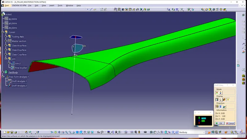
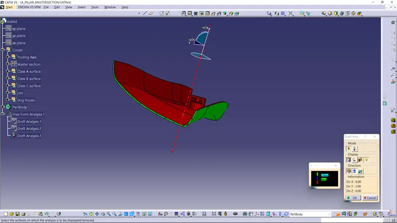
- Displays a color gradient on the faces of selected bodies to help evaluate the manufacturability of your design. Select the bodies to evaluate and the axis to define the direction. Use the options to refine the gradient display. In Catia, we use the feature draft analysis tool for this.
- Select the feature draft analysis tool.
- Then place the compass in the catia on the tooling axis we created. And press the lock symbol appear on the draft analysis window.
- Then place the cursor and click on the model to do the draft analysis.
- The color appear on the model will indicate the draft angle given on it.
- Green color indicate the draft angle which is equal to and above the given input angle.
- Red color indicate the draft angle which is below the given input angle.
- Majorly we use draft angle as 3 degree.
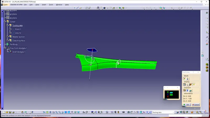
CLASS A SURFACE
- Class A surface is already given as a input.
- If the surface is did not join use the join command and join in it.
- And make as complete class A surface.
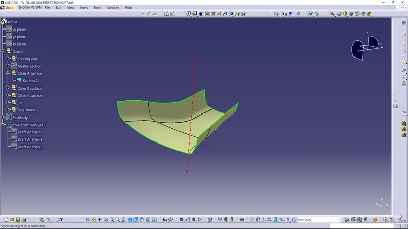
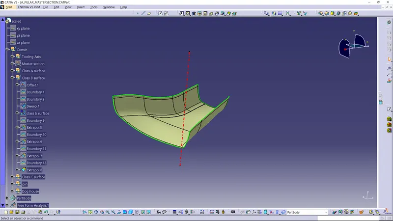
CLASS B SURFACE
- Create the Class B surface with the help of master section if master section is did not given then use offsetting method for creating class B surface.
- In some cases direct offset method is working.
- And the other cases is did not work. At the time we use the offset the class A surface into separate part
- Then we use different command on the catia to make as a complete class B surface.
- Command which we use are, Extract, Offset, Untrim, Extrapolate, Sweep, Multi section, Trim, Join, Boundary, Fillet, etc…,
- The class B surface is created on the offset distance of 2.5mm.
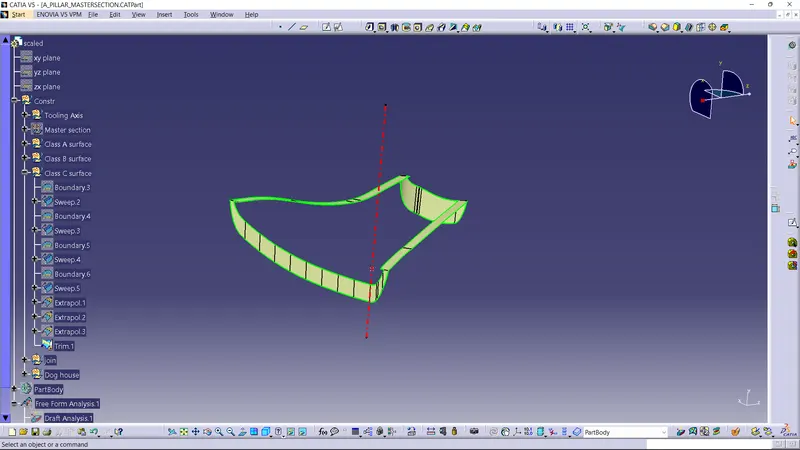
CLASS C SURFACE
- The surface which connect the Class A and Class B is known as Class C Surface.
- Class C surface is majorly created by using the sweep command.
- In The sweep we use the line type with draft direction and the line type with reference surface.
- Then the command on the catia like Trim, Join, Extrapolate, we create the complete class C surface.
CLASS A AND CLASS C JOIN
- The Class A surface and the Class B surface is join to make single surface.
- By using the join command we join the Class A And Class C surface.
- The merging distance for joining is 0.003mm.
CLASS A & B & C JOIN
- The joined Class A and Class C is trimmed or joined with the Class B surface to make a closed surface.
- After the trimming the three surface are combined into one closed surface.
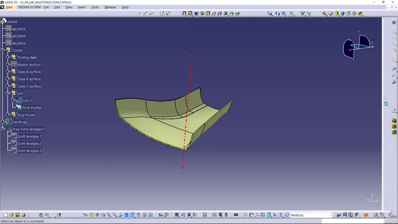
CLOSED SURFACE INTO CLOSED SOLID
- The closed surface we created on the generative shape design is shifted into the part design workbench to make closed solid.
- There is option called closed surface use the option to make closed solid.
- Then do the draft analysis for the closed solid model.
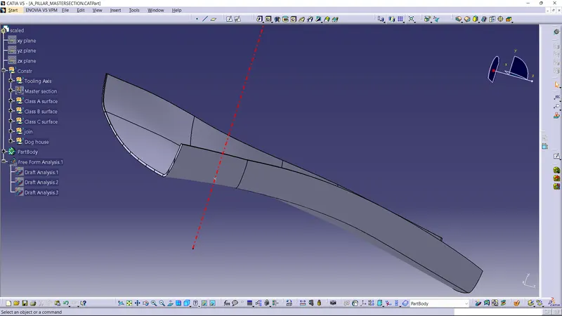
DRAFT ANALYSIS FOR COLSED SOLID MODEL
- Displays a color gradient on the faces of selected bodies to help evaluate the manufacturability of your design. Select the bodies to evaluate and the axis to define the direction. Use the options to refine the gradient display. In Catia, we use the feature draft analysis tool for this.
- Select the feature draft analysis tool.
- Then place the compass in the catia on the tooling axis we created. And press the lock symbol appear on the draft analysis window.
- Then place the cursor and click on the model to do the draft analysis.
- The color appear on the model will indicate the draft angle given on it.
- Green color indicate the draft angle which is equal to and above the given input angle.
- Red color indicate the draft angle which is below the given input angle.
- Majorly we use draft angle as 3 degree.
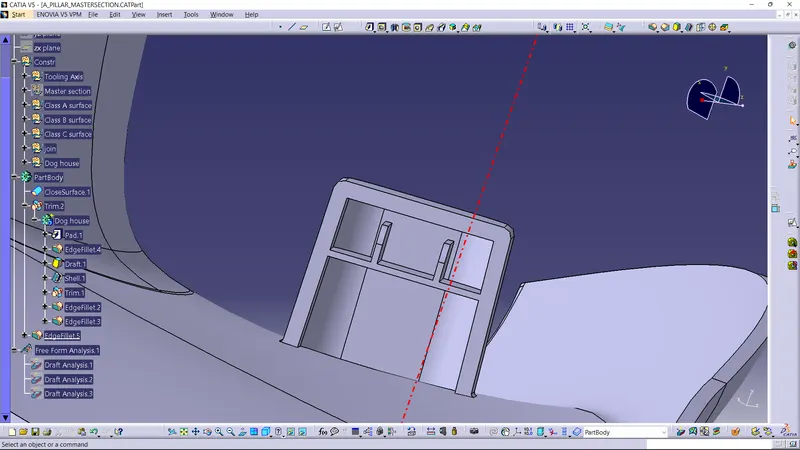
DOG HOUSE CREATION
- Dog house is an engineering feature used in plastic trim design. Dog houses are used as supporting feature. Sometimes other engineering features like snaps; locators etc. are mounded on them to increase their strength. Dog houses are subjected to draft analysis to prevent breakage of the component during ejection from mould cavity. Dog house and other engineering components are built on B-surface.
-
DESIGN CONSIDERATION FOR PLASTICS:
1.WALL THICKNESS:
Thick sections waste material and are simply uneconomic. So solid shapes that would do the job well in wood or metal must be transformed to a 'shell' form in plastics. This is done by hollowing out or 'coring' thick parts so you are left with a component which regardless of complexity is composed essentially of relatively thin walls joined by curves, angles, corners, ribs, steps and offsets. As far as possible, all these walls should be the same thickness. Wall thickness guide range is 0.75 mm to 3 mm for reinforced materials 0.5 mm to 5 mm for unreinforced materials.
WALL THICKNESS(W)=0.70*(NOMINAL THICKNESS OF PLASTIC MATERIAL)
2.CORNER RADII
Properly designed corners will make a big difference to the quality, strength and dimensional accuracy of a moulding. But there is another benefit too. Smooth curved corners help plastic flow in the mould by reducing pressure drops in the cavity and minimising flow-front break-up. Internal radii should be at least 0.5 and preferably 0.6 to 0.75 times the wall thickness.
CORNER RADII= (0.6-0.75) * (NOMINAL THICKNESS OF PLASTIC MATERIAL)
3.DRAFT ANGLE:
Tooling must be cleared for easy ejection of the component, from the core cavity. In order to clear tooling certain value of draft is given to the component. Minimum of 2-3deg is provides on all plastic components.
DRAFT ANGLE=2-3 DEGREE
4.FILLETS:
Fillet on the inner side = 0.25 * Thickness of the plastic material
Fillet on the outer side = 1.25 * Thickness of the plastic material
Fillet on the coring edges = 0.25 * Thickness of the plastic material
Coring thickness = 0.40 * Thickness of the plastic material
CONCLUSION
- Tooling axis are created.
- Draft analysis for the class A surface are performed.
- The Class B and Class C surface are created.
- Closed solid of the coinA Pillar with Mastersection are created.
- Draft analysis for the solid model are performed.