Week 9 - Project - A pillar Design with Master Section
DESIGNING A PILLAR USING MASTER SECTION
OBJECTIVES
- To improvise the Class A surface by resolving bad patches and adding flanges to it.
- To create A pillar solid model with the help of improvised class A surface.
- To create B side features for the A Pillar using the master section given to us as an input.
INTRODUCTION
MASTER SECTION: Master sections development takes place during feasibility check and concept validation stages of the product life cycle. These are typically the guides for design requirements and which decides the component packaging after the development of the concept design, i.e class A surfaces.
Master section helps us to decide the feasibility of the concept design, the clearances, the packaging and the fixation strategy of a component before converting the concept design into a solid 3D engineering design.
During the period of vehicle concept design the evaluation of the master section performance depends mainly on the reference vehicle data and experience of structure design engineer.
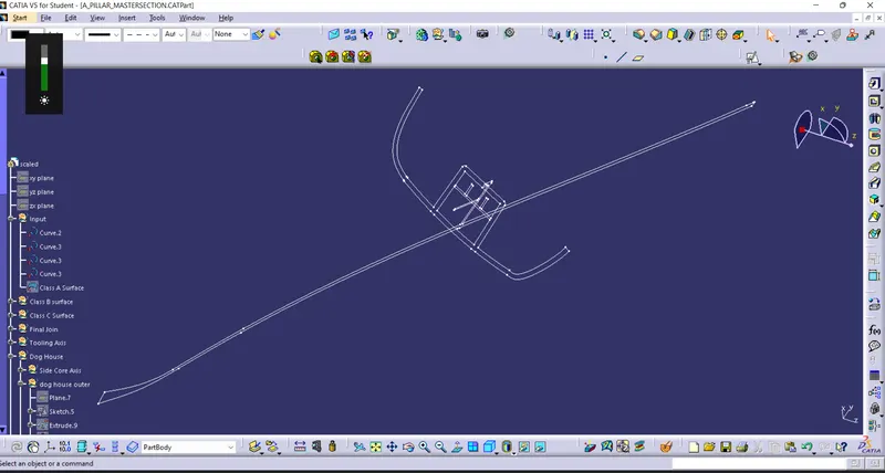
GIVEN MASTER SECTION
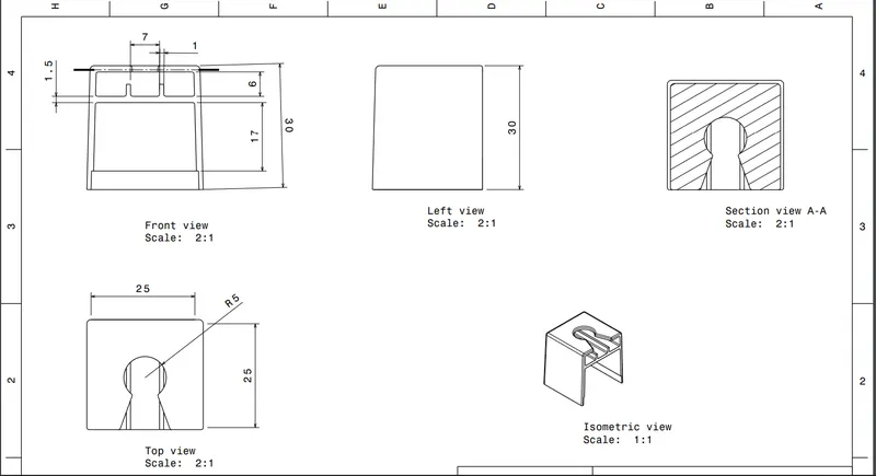
GIVEN DOG HOUSE DRAWING
Given Class A surface :-
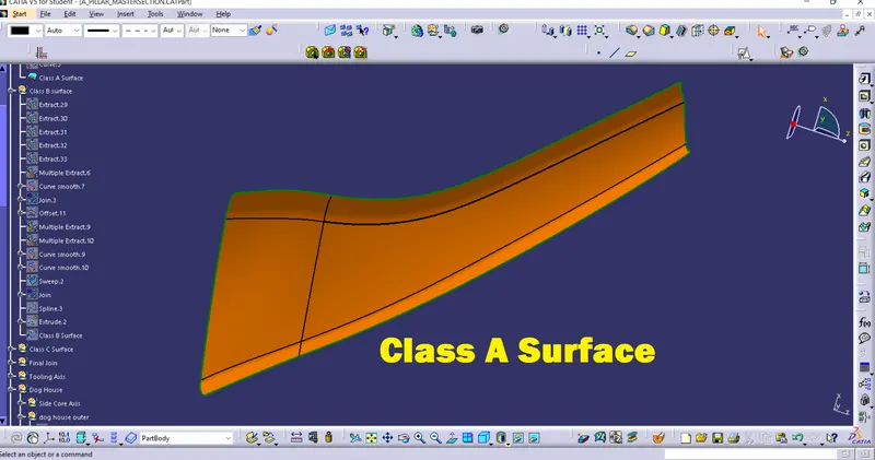
Tooling Direction :-
Tooling axis is the direction in which mold or core and cavity opens. The ejection of the part from mold depends on the draft. A zero draft can result in difficult or no ejection due to shrinkage. It is recommended to add a minimum of 0.5 to 1 degree of the draft for non-textured surface & 3 to 5 degree of draft for textured surfaces.
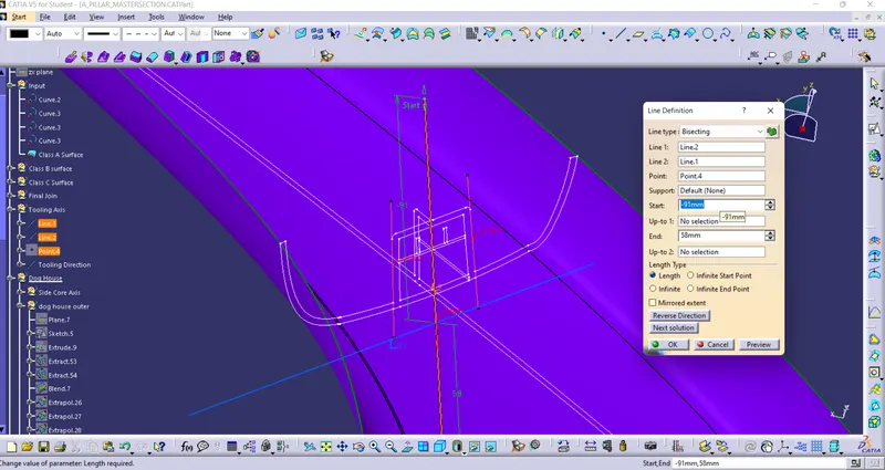
Procedure to create the tooling axis using bisecting method :-
following Class A surface is provided to design the A Piller Design using Given Master section Create Two Intersecting line
and create Tooling Axis using Bisecting Both lines
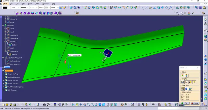
Draft analysis For Class A Surface:-
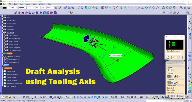
Draft analysis is performed based on color ranges identifying zones on the analyzed element where the deviation from the draft direction at any point, corresponds to specified values. Minimum draft angle is considered as 3 degree.
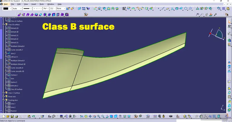
B-Surface :-
Class B-Surface is extracted from the A-surface and it is offseted at 2.5mm in downward direction.
Missing surfaces create with swept surface and Join

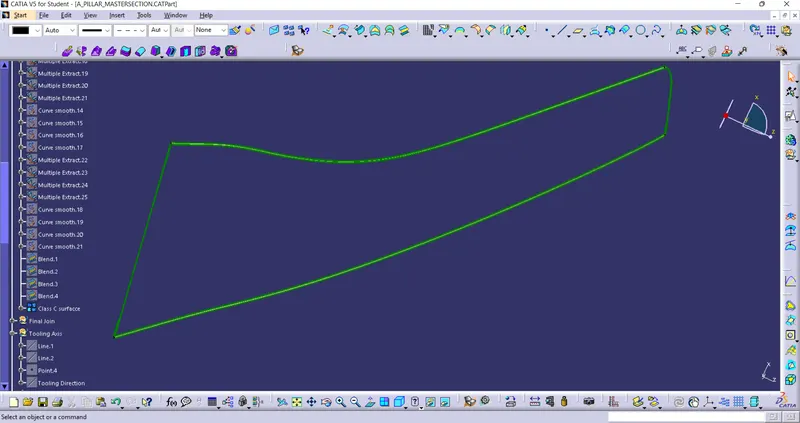
CLASS C SURFACE
I created Class C surface using both surfaces boundary to create A blends
FINAL SURFACE
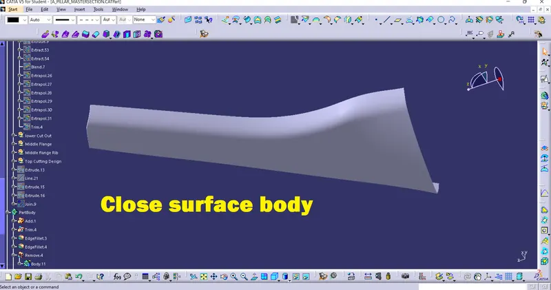
Joined A , B and the surfaces without any boundary.

Final Solid Body using close surface
CREATION SIDE CORE TOOLING AXIS
Apart from A surface and C surfaces we also need to consider the B side attachment features in order to create the tooling axis because all the attachment features have a large number of surfaces parallel to the tooling direction.
For creating the tooling we can take reference from the master sections of the B side features and create tooling axis accordingly as shown in the figures below.
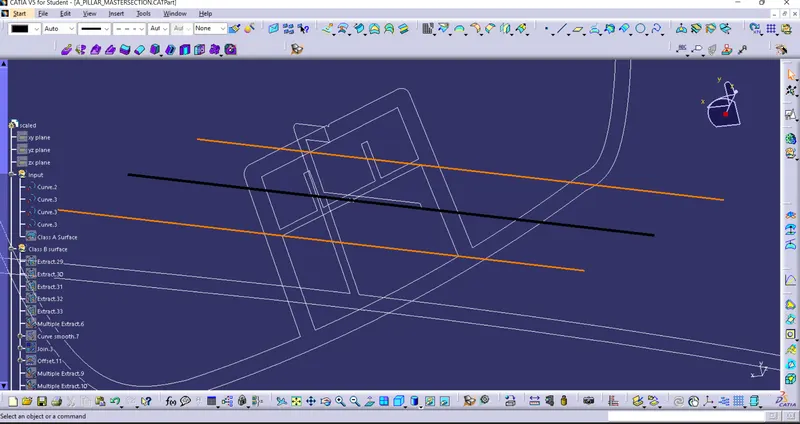
There are some of the attachment features like doghouse that needed a side core during moulding operation so for such B side features we have to create a side core tooling axis.
For the creation of side core tooling axis again we can take refrences from the master sections of the A pillar. This is shown in the figures below.
DOG HOUSE & RIBS
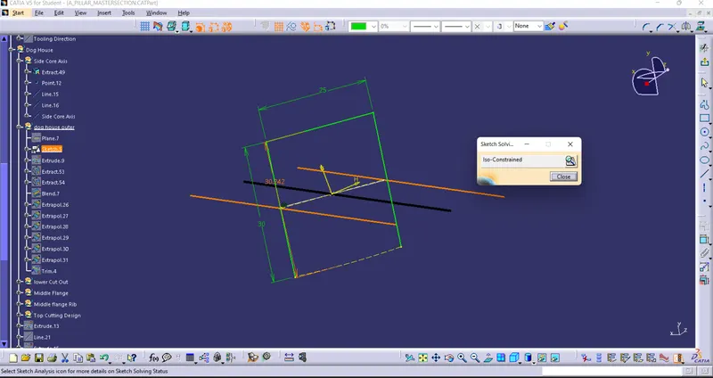
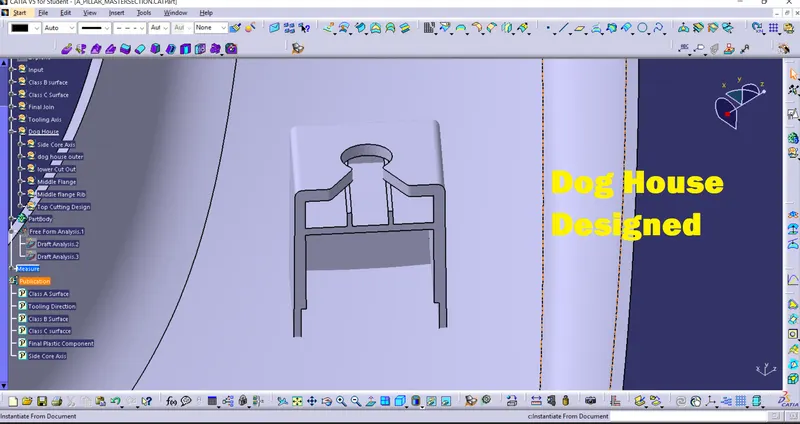
Create the dog house & ribs as per master section.
DOG HOUSE Sketch With Iso-Constrained And Positioned sketch
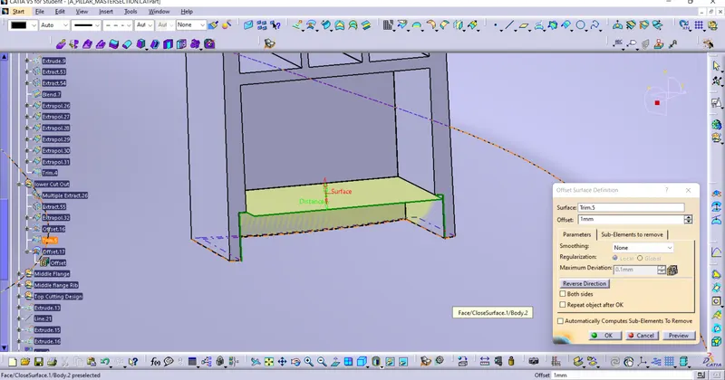
Lower Section Cutout:-
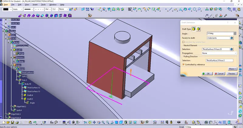
Draft to the dog house
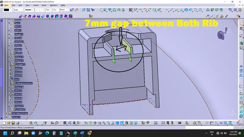
Created Middle Flange Rib Using Extrude and Thick surface
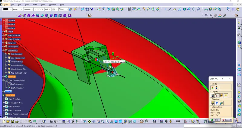
Draft Analysis for Dog House Using Side Core Axis
Draft Analysis for Final Component Using Tooling Axis
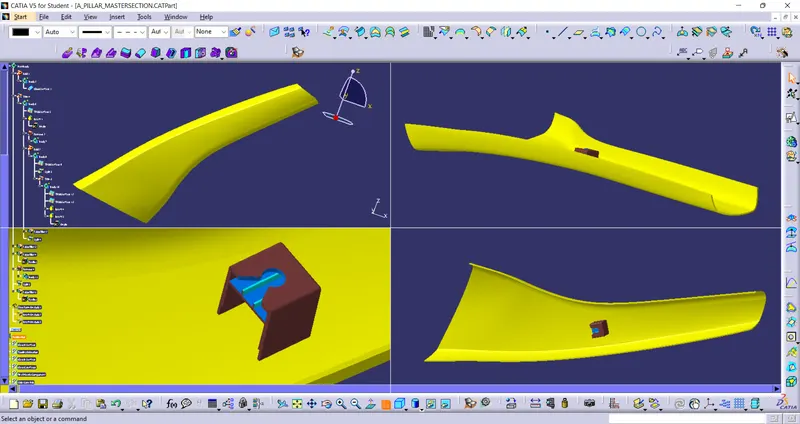
Views-
Dog House
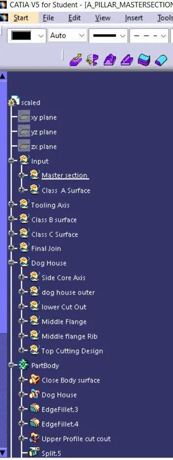
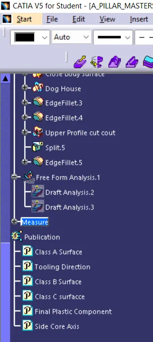
Tree Structure:-