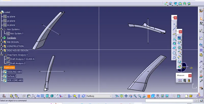
Week 9 - Project - A pillar Design with Master Section
AIM
This Report aim is to perform draft analysis for the given surface by defining a tooling direction appropriate to the shape of the surface and also to create the class-B,class-C surfaces and final closed body with the help of given Class A surface of A pillar Design with Master Sectionand based on design rules.
THEORY
Class A surface
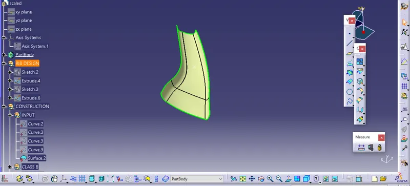
This is the styling surface which provides the aesthetic features of a component. A designer starts the design of component from a class A surface.
Given class A surface
Class B surface:
Class B surface is obtained by offsetting the class A surface by the component thickness value. This B surface contains all the engineering features of the component. So it is also called as Engineering Surface.
Creation of class-B surfaces:
B surface is created by offsetting the class A surface by 2mm and if there are any surfacesnot offsetted then they will be created by using multisection surface or sweep command.
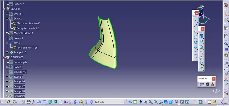
Class C surface:
Class C surface is created along the tooling direction of the component and it connects the class A and class B surfaces.
Creation of Class-C surface:
C surface is created by using boundary of A surface. with the help of sweep command surface is generated perpendicular to the edges of A surface.
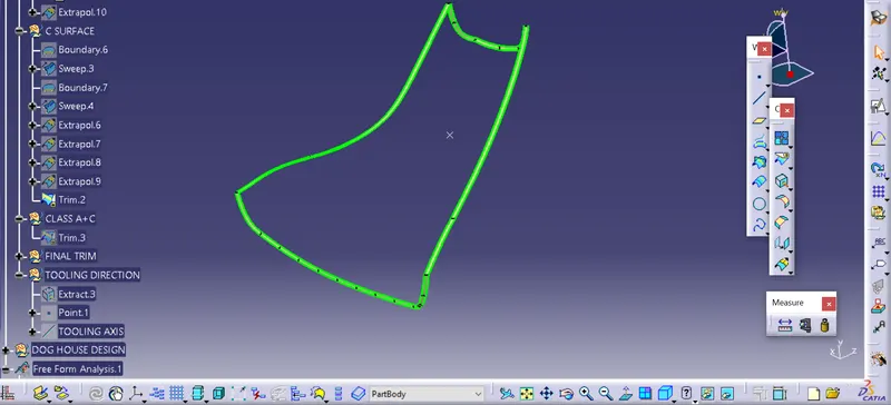
Tooling Axis:
Tooling axis is the direction in which the part is released from the mould.
Defining the tooling direction
Ideal tooling direction has to be the direction in which most of the features can be easily cleared. In this case the initial tooling direction can be assumed in the direction perpendicular to the flat surfaces and the surfaces which might be difficult to clear in this direction are identified and the initial tooling direction has to be modified accordingly. But in this case the flat surfaces and the critical surfaces are perpendicular to each other. So, the initial tooling direction can be taken as the final tooling direction.
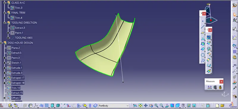
Draft analysis of Class- A
After creating a tooling axis we do the draft analysis. Before drafting we have to make sure that in the view mode it is selected for the materials.
After selecting the feature draft analysis tool we drag the compass from its position to the tool axis. Then lock the compass. After that select anywhere on the component and it will give you the result.
We change the minimum draft for the component to 3°.
We can use the running point option to check the angle of the component.
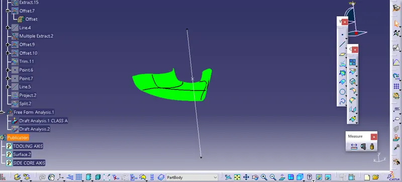
CLASS A +C
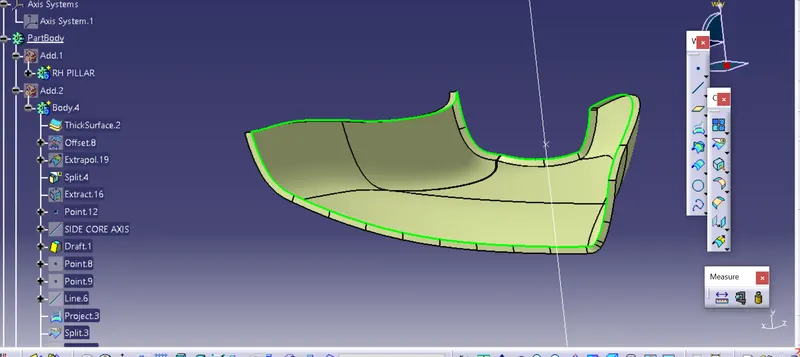
FINAL TRIM
Draft Analysis on the final component :
- The part created has to be changed to the material mode in the display frame.
- Compass is enabled and aligns it along with the tooling direction.
- The lock command is then applied to fix the compass along with the tooling axis.
- Color codes are classified and Draft angle is applied.
- Running point analysis is used to display permissible draft angles.
Draft analysis on the dog house considering the side core axis as our tooling.
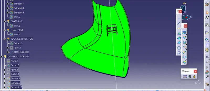
DOG HOUSE
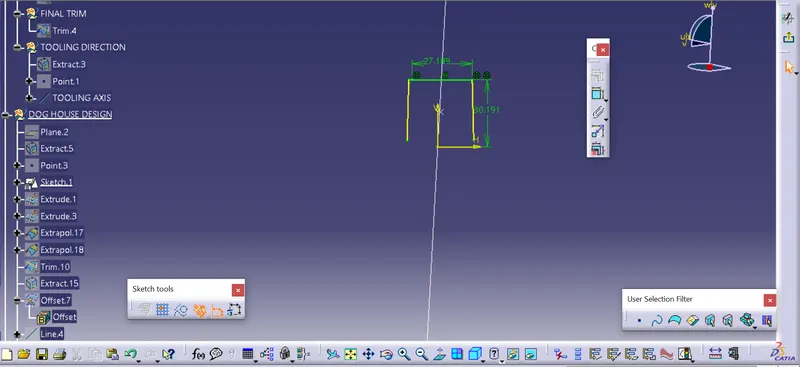
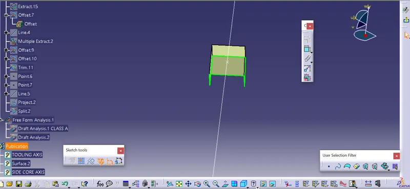
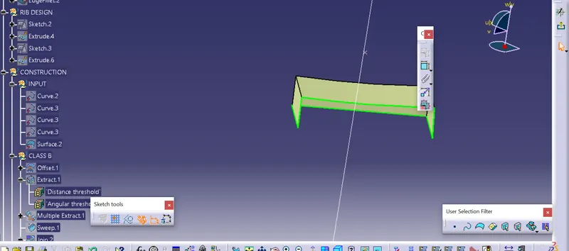
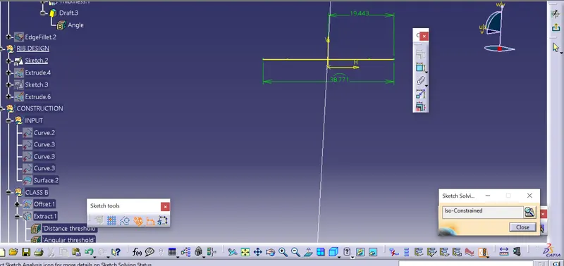
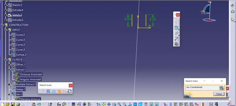
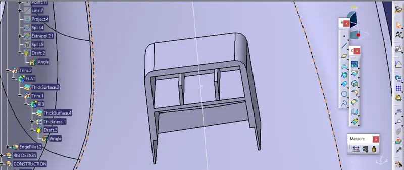
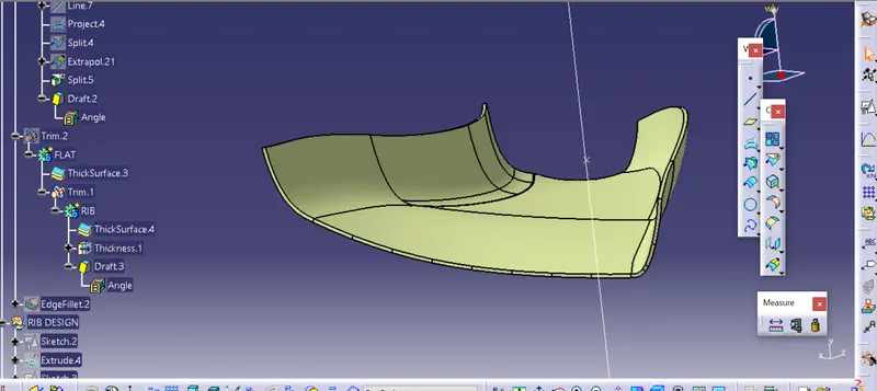
CLOSED BODY
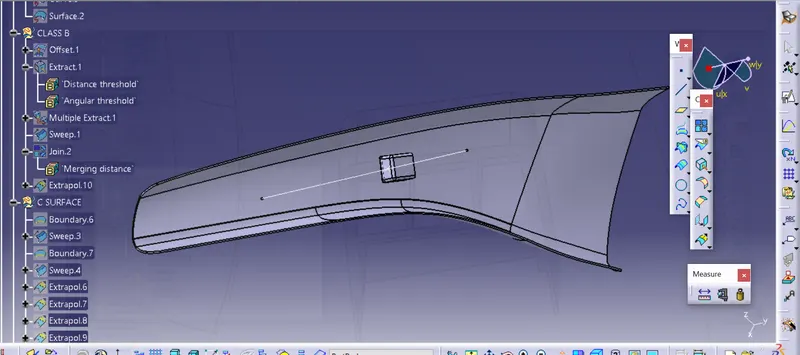
MULTIPLE VIEW