Week 9: Project 1 - Surface preparation and Boundary Flagging (PFI)
Aim: To simulate the No-hydro case for the PFI using converge CFD.
Objective:
- Boundary Flagging.
- Surface preparartion.
- Show mesh on dfferent slices at different time steps.
- In an animation, all the valves and piston should move according to the crank angles.
Surface preparation and boundary flagging
- In the first step, we have taken the geometry and spilt it into the meaningful boundaries.
- In the first step we have to goto boundary`rightarrow`flag and then choose the multiple boundaries.
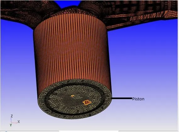
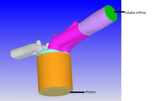
- Choose the angle method, and select the bottom boundary and name it piston.
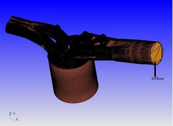
- Then again choose the by angle method and select the boundary and name it inflow boundary.
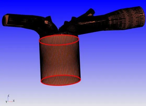
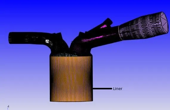
- Next step we isolate the boundary of liner. For that we are going to Boundary `rightarrow`Fence `rightarrow`By select edges and also choose the By arc method. And select the two edges as shown the red lines in the figure and name it to liner.
- Now we flag the cylinder head by selecting the following boundary fence because we want to sepearate cylinder head.
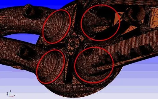
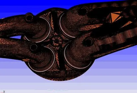
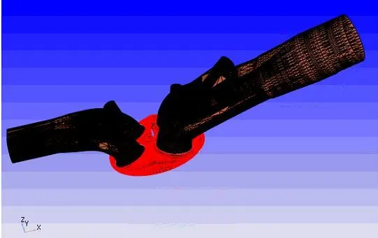
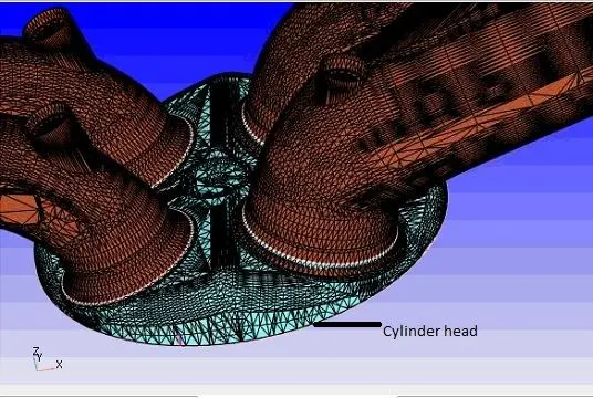
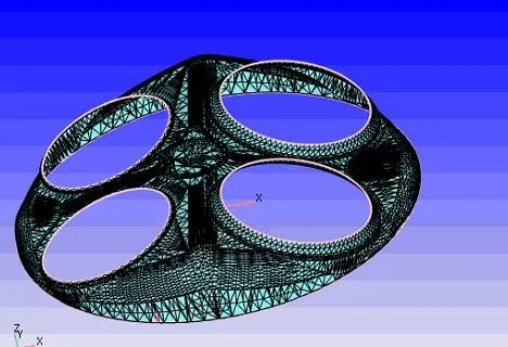
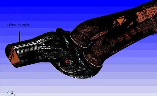
- Now we flag the exhaust port. For that choose the by angle method and select the exhaust port as shown in the fig (the red colour shows) and then name it to exhaust port.
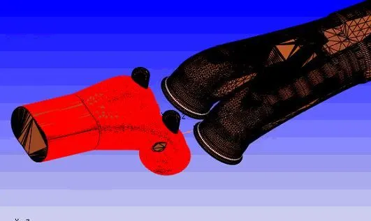
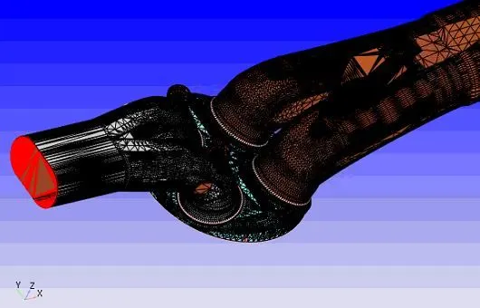
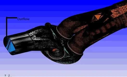
- Also choose the by angle method and then select the outflow boundary as shown in the below figure.
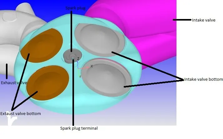
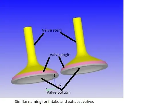
- In the next step, we divide the valve into three different steps. For that we are going to boundary fence and divide the valve into three different parts as shown in the below figure
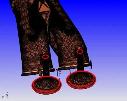
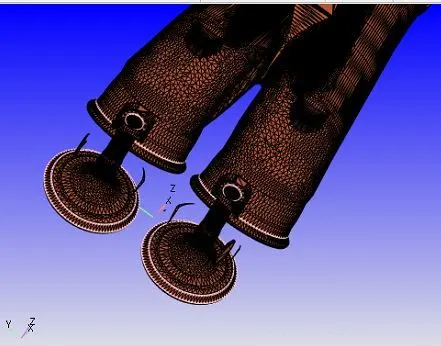
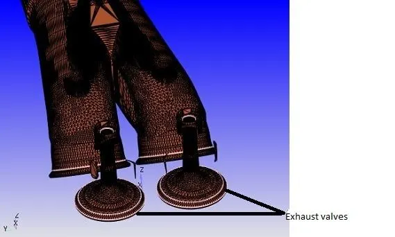
And then goto boundary flage and select the following surfaces and name it intake valve top. And also gave the boundary flag of the remaining boundaries of exhaust valves.wich is exhaust valve angle and Exhaust valve bottom.
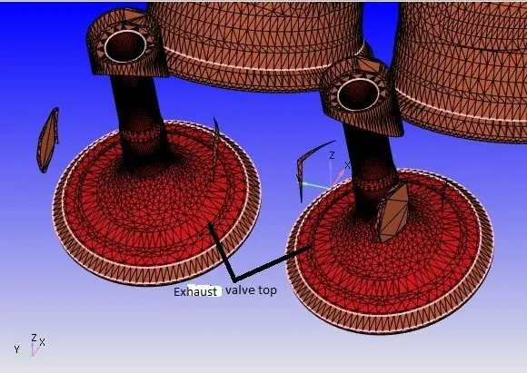
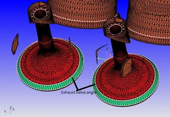
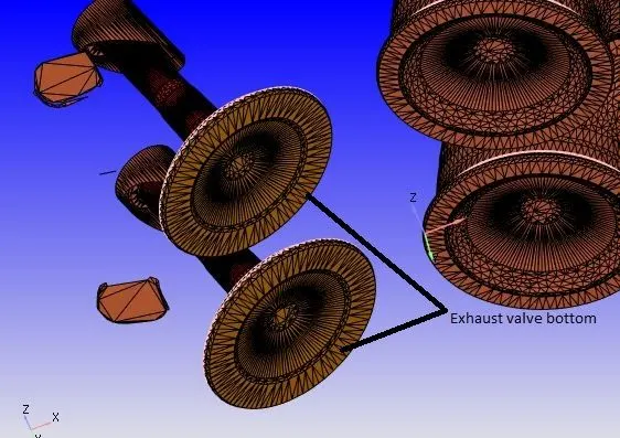
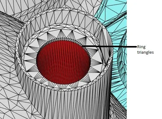
- In the next step hide all the parts which we flag the boundaries and choose the box pick and select the following as shown in the figure and this red selection is added to the exhaust port. And also made the ring triangle to a part of exhaust port. Select these ring tringles as shown in the below figure. Then goto boundary flag and choose the boundary fence method and add to exhaust port.
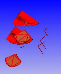
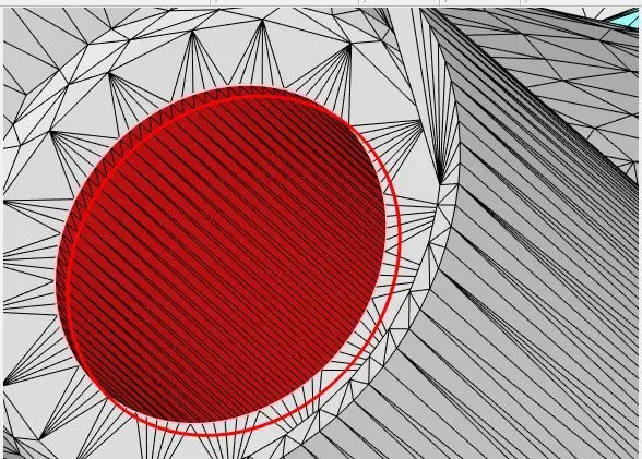
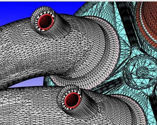
- Above steps conclude our exhaust port and valve flagging and other things.
- Now we hide everything and only enable the boundary which is intake port. If we choose the angle method but we are unable to choose the intake port. To resolve this problem we redisplay everything and then goto boundary fence and select Reconstruct fence from existing boundaries that automatically separate the intake port and inflow boundary as shown in the below figure.
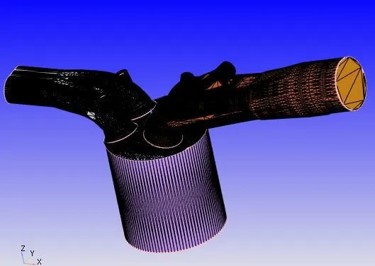

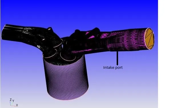
- Now we are using the angle method to capture the intake valve bottom. And using the boundary fence method to select the intake valve angle and top.
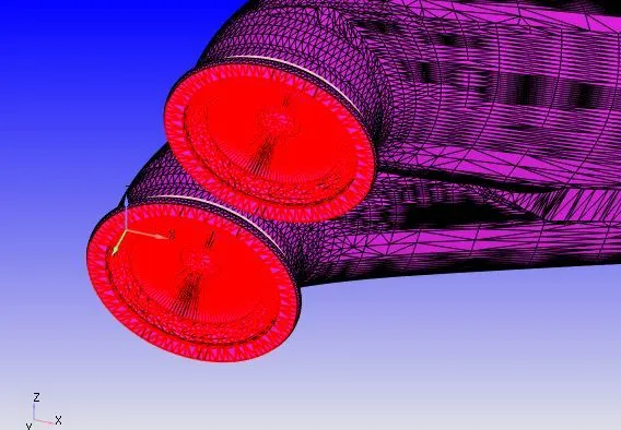
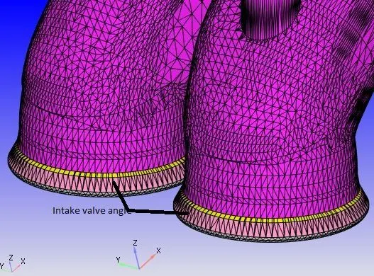
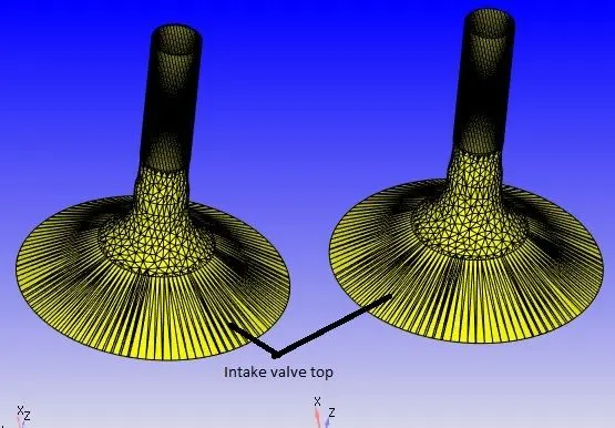
- To avoid the intersection errors we translate the valve. How we do this we are goto transform `rightarrow`translate `rightarrow` Direction vector.
- For that we are going to Measure `rightarrow`Direction `rightarrow`arcnormal and select the three points and make sure that these three points are on the same circle.
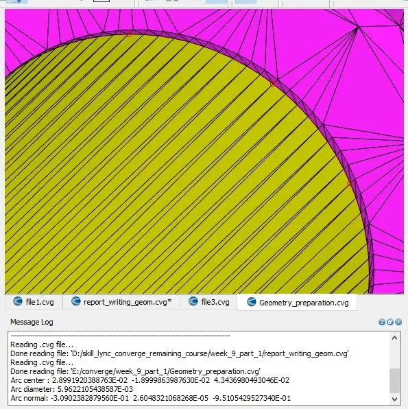
- And then copy the arc normal and paste in the transform and then goto translate and then goto selected boundary(Intake valve angle, intake valve top, intake valve bottom) and paste in the direction vector.
- And in the translation amount put the value 0.001.
- When we check the diagnosis, we can see that most of the intersection errors are gone.
- In the next step we fix the open edges issues, which is clearly see in the below figure.
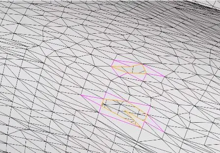
- Now we patch these edges by using the tool repair and then goto patch and then goto and also select the open edge method and also select the triangles as shown in the figure. Also click on the auto assign boundary for new triangles.
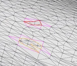
- In the next step check again the diagnosis, we can see that all the open edge errors are gone but few are still there. To check these errors click on the open edge and then click on show edges. If you click on neighbor it will show you some contact. We can see this thing in the following fig.
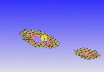
- In the view option just pick a triangle and then click on any and then click on triangle and we can see that the it shows that this portion which belong to the piston, then you can apply this thing to all other parts. And also patch all the surfaces which are open by using the same procedure as told in the above steps. Then check the diagnosis, we can see that all the open edge errors are gone. And only the normal orientation errors are still there.
- We also flag the spark plug terminal and spark plug.
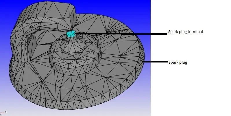
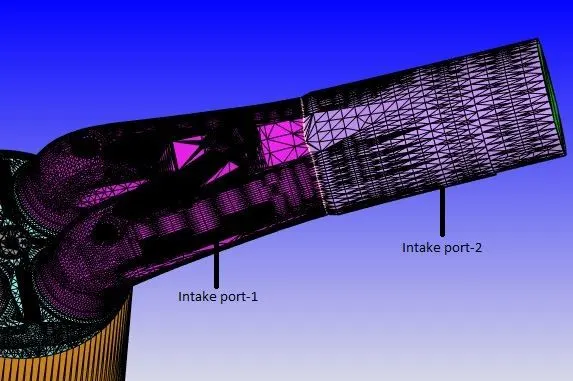
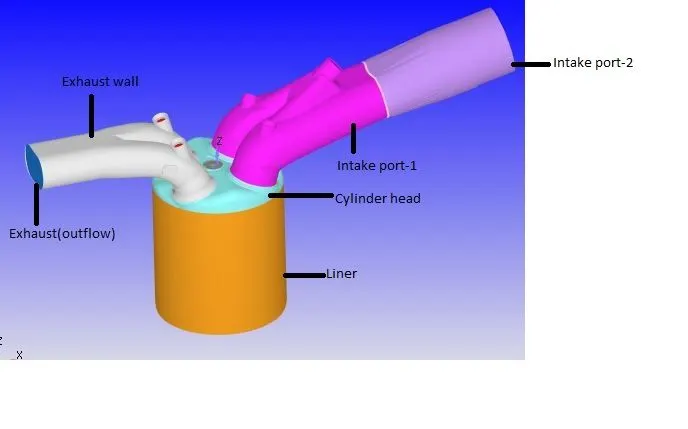
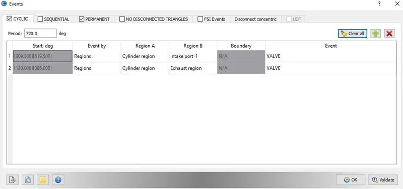
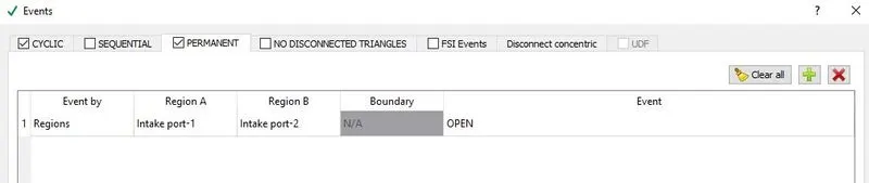
- We also divide the intake port into two parts. There are two reasons to divide the port into two parts. The first reason is for the valve and the reason why we spilt the valve into three parts is that the software except us to do this. And we want to restrice the flow that is coming from intake to the cylinder during the compression and power stroke. And the software does not know that your intake system is a intake system and similarly it does not about the combustion chamber. So basically we use the events to basically control the flow that is take place the first and second region. And the reason behind we divide the valves into three parts because it helps us to create events easily. so that is the reason number one.
- As far as the port is concern we divide the port into two parts is to provide the batter initial condition.
- First of all check the normals we can see that these are pointing outside. To point inward goto transform and then goto normal and select the triangle and then hit apply. It will automatically point inward.
- In the end again check the diagnosis. We can see that all the errors are gone now. And this will end the first phase of your project.
Final Flagging
Case Setup for the no-hydro
- Open the case setup.
- Open the crank angle based and add the following properties.
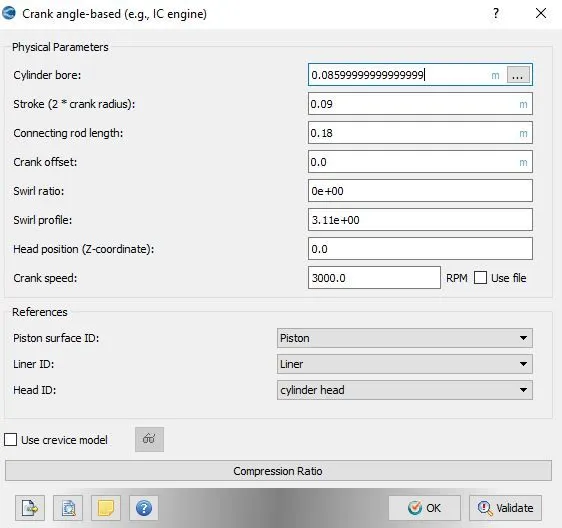
- Open the materials and do the folllowing settings.
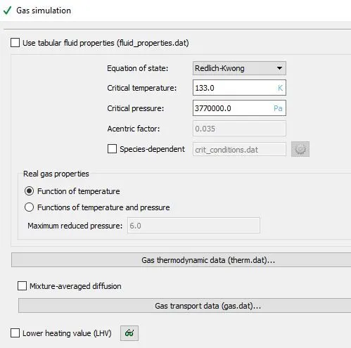
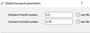
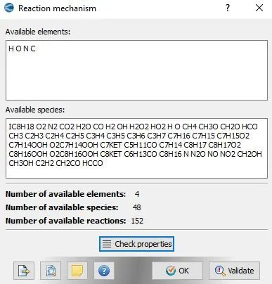
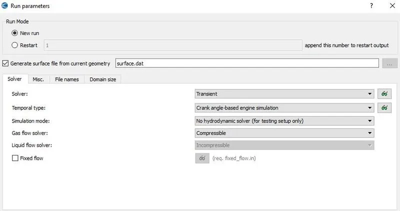
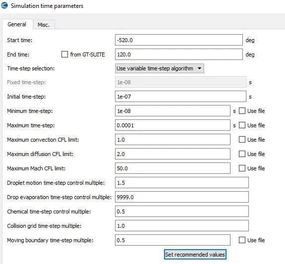
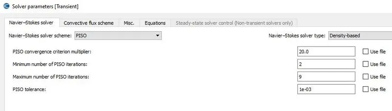
- Then open the simulation parameter and do the following setting.
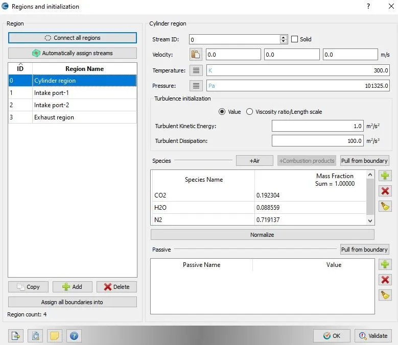
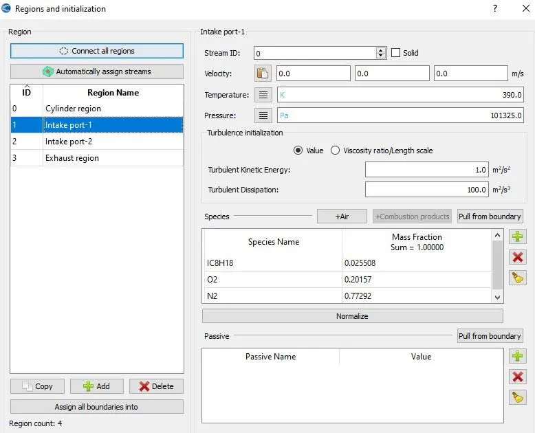
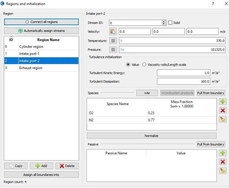
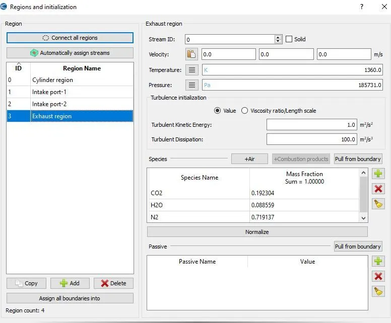
- First of all open the regions and initializations and add the four regions as shown in the below figure.
- Add the following events
- Now open the boundary conditions and define the following regions to the boundaries.
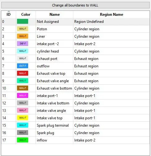
Region initializations and boundary conditions
|
Regions |
Boundary name |
Boundary type |
Boundary motion |
Pressure |
Temperature |
Species |
Motion details |
Region Initial pressure |
Region Initial temperature |
Region Initial species |
|
Intake port-1 |
inflow |
inflow |
N/A |
101325 |
363 |
O2: 0.23 N2: 0.77 |
- |
101325 |
390 |
IC8H18: 0.025508 O2: 0.20157 N2: 0.77292 |
|
Intake port-1 |
wall |
stationary |
- |
425 |
- |
|||||
|
Intake port-2 |
Intake port-1 |
wall |
stationary |
- |
425 |
- |
101325 |
370 |
O2: 0.23 N2: 77 |
|
|
Intake valve angle |
Moving |
- |
480 |
Intake_lift.in file |
||||||
|
Intake valve top |
Moving |
- |
480 |
Intake_lift.in file |
||||||
|
Cylinder |
Piston |
wall |
Moving |
- |
450 |
Piston motion |
101325 |
300 |
CO2: 0.1932 H2O: 0.088525 N2:0.71913 |
|
|
Liner |
stationary |
- |
450 |
- |
||||||
|
Cylinder Head |
stationary |
- |
450 |
- |
||||||
|
Spark-plug |
stationary |
- |
550 |
- |
||||||
|
Spark plug terminal |
stationary |
- |
600 |
- |
||||||
|
Exhaust valve bottom |
Moving |
- |
525 |
Exhaust_lift.in file |
||||||
|
Intake valve bottom |
Moving |
- |
480 |
Intake_lift.in file |
||||||
|
Exhaust region |
Exhaust port |
Wall |
stationary |
- |
500 |
- |
101325 |
1360 |
CO2: 0.1932 H2O: 0.088525 N2:0.71913 |
|
|
Exhaust valve angle |
Moving |
- |
525 |
Exhaust_lift.in file |
||||||
|
Exhaust valve top |
Moving |
- |
525 |
Exhaust_lift.in file |
||||||
|
Outflow |
outflow |
N/A |
101325 |
Backflow:800 |
CO2: 0.1932 H2O: 0.088525 N2:0.71913 |
- |
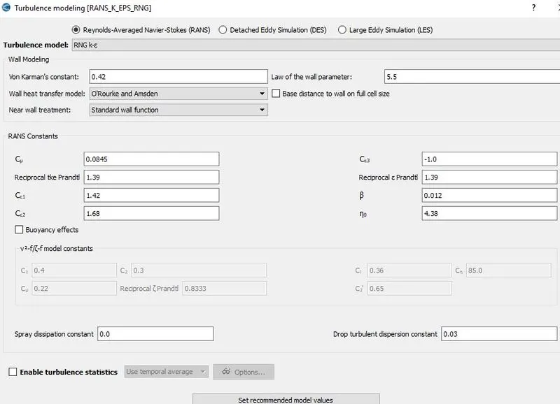
- Open the physical models and add the turbulence model.
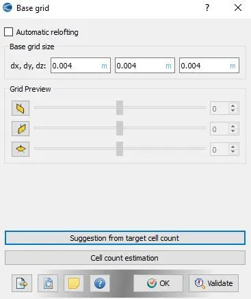
- open the base grid window and add the values. In the no-hydro case as we have the restriction of cells thats why we don't add the fixed and adaptive mesh refinement.
- Retain the same setting in the output and post variable selection.
Mesh
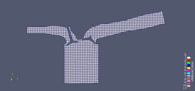
Animation video:
In the above figure, we can easily see the animation of 4-stroke port fuel injection. All the valves and piston motion are easily visible. In the above animaton, first stroke is the exhaust stroke and second stroke is the intak stroke and third stroke is the compression stroke and fourth stroke is the power or ignition stroke.
Errors
- While doing the boundary flagging and surface prepaing i am facing the lot of errors. The most common type of errors i am facing is the intersections errors, open edges and Normal orientation.
- Doing the boundary flagging is also a time taking process. While creating a boundary fence at the different parts of the geometry is also very technical.
- I am also facing the error of valve translation.
- If we gave the wrong value of start and end time in the simulation time parameter then the full cycle engine simulation is not presented here.