Week 9: Project 1 - Surface preparation and Boundary Flagging (PFI)
Aim: To perform surface preparation and boundary flagging tasks in IC Engine case and setup a No Hydro simulation.
Theory:
Port fuel injection (PFI):
In the port fuel injection, the injector is fitted in the inlet manifold, near to the inlet valve. In this fuel is injected into the intake port so that the fuel is mixed with the incoming air. Every cylinder is provided with separate injector in multi cylinder engine.
Boundary flagging:
In converge the geometry are made up of several triangles. The boundary flagging means the assigning the name to the group of triangles like where we want to indicate it as the separate boundary from other boundaries. Assigning the names to the group of triangles and making it as a boundary is called boundary flagging. By doing this it is easier to apply the conditions at each boundary and also, we can define how that boundary behaves during the simulation. One more benefit of doing this is that, if the geometry has internal parts, if we want to select those parts, we can first make outer boundaries then after hiding this boundary we can see and select the parts easily. The methods that are available in the converge to flag the boundaries are Any, Angle, Boundary fence, surface, By Fence neighbour, By manifold and by area.
1.Any:
In this method we can select the triangles separate easily and group it together to make boundaries. This method is useful for simple geometries but for complex geometry it is time consuming and requires a lot of effort to select the triangles.
2.Angle:
In angle method it uses the angle between normal of the triangles while selecting the triangles. In this there is an option for setting up the angle between the normal of a triangle, so that all the triangles are selected at a time.
3.Boundary:
This method is used the triangles of a boundary that has already been flagged and needs to be reflagged into the single boundary.
4.Boundary fence: This method is used where we want to create separate boundaries in a part that are combined in the geometry. Before using the boundary fence, first of all the fence is to be created around the part where we want to assign the separate boundary, then after by using the boundary fence option the part is used to assign the boundary.\
Surface preparation:
For the simulation of the particular project, first we need to import the geometry from the design software’s, where the geometry is created and converted it into the .stl file. The .stl file is the file which is accepted by the converge to import the geometry into the converge. Though the geometry is made perfectly in design software’s while converting it into the .stl file can get issues which throws the error in the converge studio. It requires some cleaning up and setting the geometry before the case setup. For this diagnosis tool is used to check for the errors in the imported geometry. In diagnosis the following are checked:
1) Intersections
2) Non-Manifold problems
3) Open Edges
4) Normal orientations
1) Intersections:
It means that a triangle is passing through the one or more triangle so because of it, in converge it creates the intersection error. Basically, in converge every triangle is connected by the common edge or common vertex.
2) Non-Manifold problems:
Non manifold problem occurs when one edge is shared by more than two triangles i.e., for all three triangles are connected to the common edge. But in converge it should be shared by two triangles only. But in some cases, like heat transfer taking place from solid to fluid or fluid to solid, the geometry should in such away that there will the need of non -manifold edges.
3) Open Edges:
Open edges are created when the single edge is shared by the one triangle. We already know that in converge each edge is shared by two triangles. So then open edges are to be closed by used patch tool, stitch tool.
4) Normal orientations:
In converge the direction of normal of every triangle in a geometry either point inside fluid domain or outside the fluid domain. If the fluid is flowing inside the geometry like pipe flow, then the normal should point towards the fluid domain. If the fluid is flowing over a flat plate, then the direction of normal should point outwards.
Assigning boundaries and cleaning up the errors in the geometry:
Here the port fuel injection of SI engine geometry is imported into the converge and the errors showing in it, after running diagnosis are shown below.
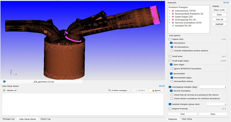
The main parts of the PFI are inlet port, exhaust port, spark plug, liner, cylinder head, piston. Then to solve the errors showing in the geometry, first of all boundary flagging is done by assigning different boundaries. So that flagged boundaries are easily hidden and other parts are flagged.
In the above figure we can see some highlighted colour on the inlet port side which is near to the inlet valve, which is intersection errors. This error is caused, while designing the geometry the designer created the geometry in such away that surface of the inlet port is into the cylinder head, which lead to the intersection triangles. This problem is erased by translating the inlet angle valves, inlet angle valves, inlet bottom valves to a certain extend. So, by doing this the intersections errors are minimized.
Firstly, the piston and cylinder are flagged separately.
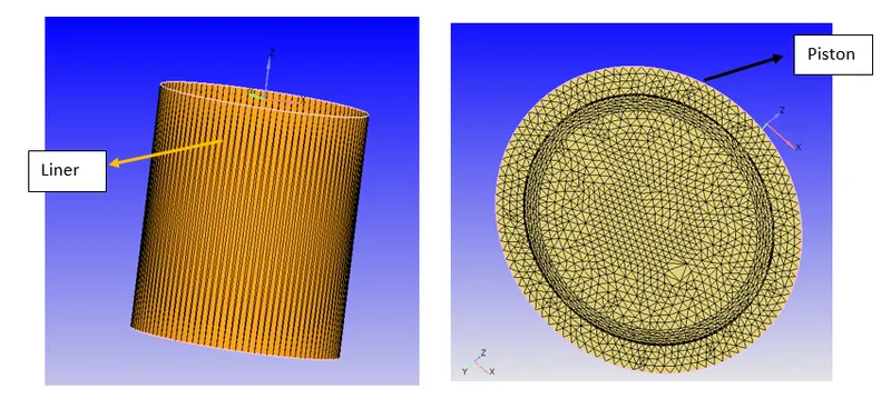
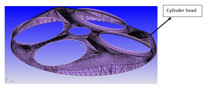
Then next cylinder head is flagged, but while flagging the cylinder head entire geometry is selected. So, to avoid this, a fence is created to separate select the cylinder head by using boundary fence method.
Create the inflow and outflow flow boundaries by at the inlet and exhaust port side.
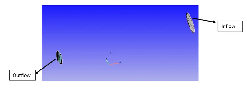
Outlet port is selected and outlet boundary is created.
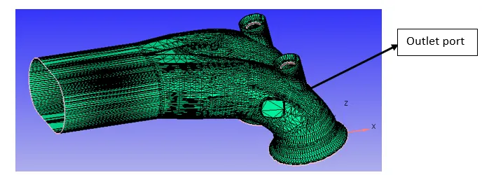
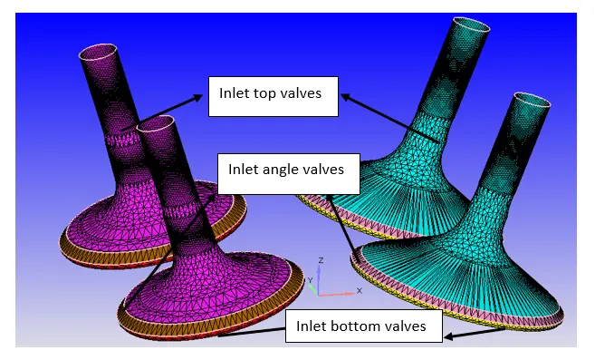
Then after hiding all the boundaries which are already been created, we can clearly see the exhaust valves. So here the exhaust valves are split into the 3 boundaries are exhaust valve top, exhaust valve angle, exhaust valve bottom. By doing this it is easily for the converge to create the events at the interference of the exhaust valve and the combustion chamber. So, we impose the condition on the valve when to open and close during the simulation. Similarly on the inlet port side also, the inlet valves are split into the 3 boundaries are inlet top valves, inlet angle valves, inlet bottom valves.
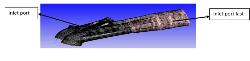
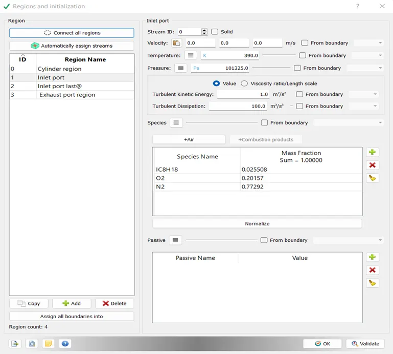
Then inlet port is selected and inlet port boundary is created and after it creating it the inlet port is divided in to the 2 boundaries. 1.Inlet port, 2. Inlet port last. This division of the inlet port is done because the fuel is injected on half of the inlet port from other half of the inlet port air is passing and it is mixed with fuel nearer to the inlet valves.
To eliminate the intersection errors, first we need to create the two fences on the inlet port side close to the valve boundaries. Then after, we measure the normal direction by selecting three points on the circumference of the circle and we get the arc normal. Then copy the arc normal coordinates and translate it by 1mm. So, the inlet valves top, angle and bottom are pushed by 1mm and intersection problem is solved.
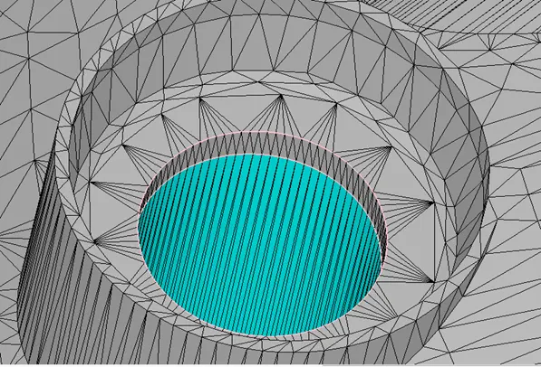
There are also some open edges and other errors are shown at the starting while we run the diagnosis. So, by using Repair- Patch option the open edges issues are resolved. The non-manifold problems are resolved by deleting the intersecting triangles. Then the normal orientations are fixed by selecting the triangle, whose normal is pointing outside direction and clicking apply.
Separate fences are marked inside the cylinder head to separate the spark plug and spark plug terminal.
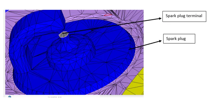
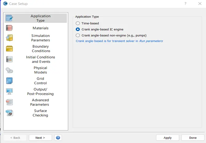
Case setup:
Setting up the application type
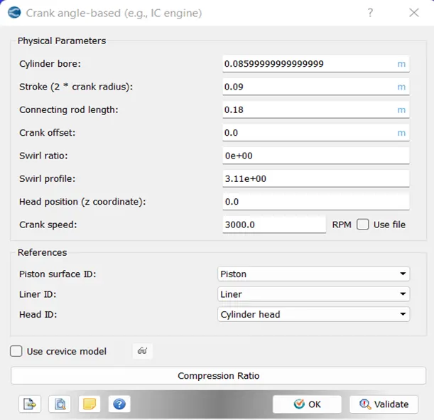
Then giving the initial data like bore, stroke length and required dimensions which is shown below
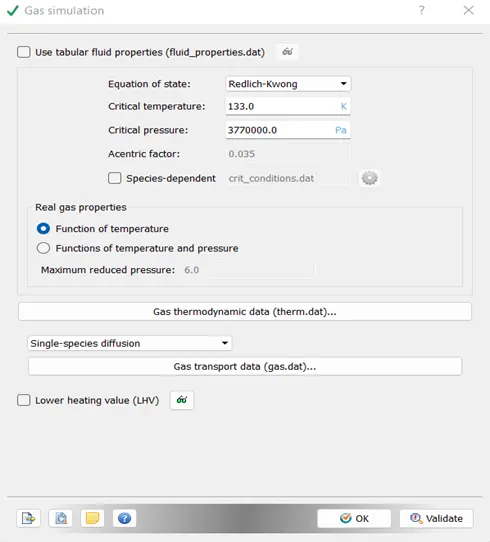
Gas simulation:
The following files are imported for gas simulation
- a) mech.dat
This file contains the PRF reaction mechanism which is involved in the combustion of fuel. This file is imported in the reaction mechanism.
- b) thermo.dat
This file contains the thermodynamic properties of the chemicals involved in the combustion. This file is imported in gas simulation.
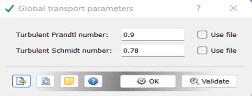
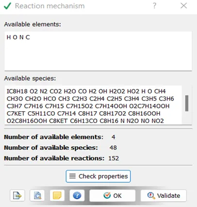
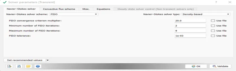
After setting up the simulation parameters, the following files should be imported for inlet and exhaust valve lift.
Following files are used as an input:
This file contains the exhaust valve profile at different crank angles during the simulation.
This file contains the exhaust valve profile at different crank angles during the simulation.
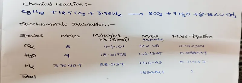
The combustion reaction is assumed to be stoichiometric and the balanced chemical reaction and stoichiometric calculations are shown below:
Each boundary is assigned to the specific region.
The boundary condition and temperature values for different boundaries are shown in the following table:
|
S.No |
Component |
Region Name |
Boundary condition |
Temperature(K) |
|
1 |
Piston |
Cylinder region |
Wall (Piston motion) |
450 |
|
2 |
Liner |
Cylinder region |
Wall |
450 |
|
3 |
Cylinder head |
Cylinder region |
Wall |
450 |
|
4 |
Outflow |
Exhaust port region |
Outflow boundary condition |
800 |
|
5 |
Inflow |
Inlet port last@ |
Inflow boundary condition |
363 |
|
6 |
Spark plug |
Cylinder region |
wall |
550 |
|
7 |
Outlet bottom valve |
Cylinder region |
Wall (Translating) |
525 |
|
8 |
Outlet port |
Exhaust port region |
wall |
500 |
|
9 |
Outlet angle faces |
Exhaust port region |
Wall (Translating) |
525 |
|
10 |
Outlet top valves |
Exhaust port region |
Wall (Translating) |
525 |
|
11 |
Inlet port |
Inlet port |
wall |
425 |
|
12 |
Inlet angle valves |
Inlet port |
Wall (Translating) |
480 |
|
13 |
Inlet bottom valves |
Cylinder region |
Wall (Translating) |
480 |
|
14 |
Inlet top valves |
Inlet port |
Wall (Translating) |
480 |
|
15 |
Spark plug terminal |
Cylinder region |
wall |
600 |
|
16 |
Inlet port last |
Inlet port last@ |
wall |
425 |
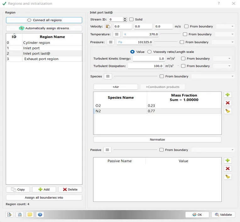
The inflow boundary has a mass fraction of 1 which contains the constituents of air i.e. Nitrogen (0.77) and Oxygen (0.23).
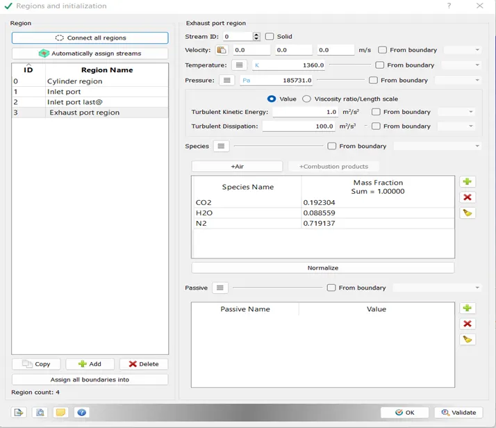
For the outflow boundary the N2, Co2, H2O constituents are in the mass fraction, as in the stoichiometric reaction it is calculated.
For the inlet and outlet valves like angle, top, bottom, the valve profiles are imported.
Initial conditions and events:
Region and Initialization:
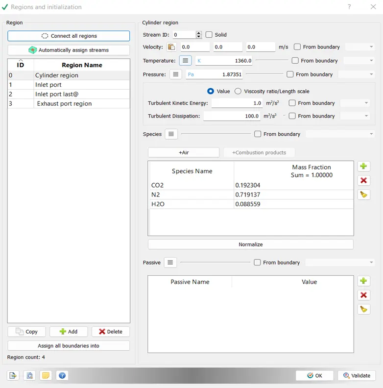
In this, 4-regions are created, they are
Cylinder region, Inlet port, Inlet port last, Exhaust port.
For Cylinder region following initial conditions are set.
Temperature is set as 300 k
Pressure is set as 101325.0 Pa
Initial velocity of the species is set to 0 m/s
Species is set as follows
CO2 - mass fraction is 0.192304
H2O - mass fraction is 0.088559
N2 - mass fraction is 0.719137
Events:
These events will create the disconnect triangles between the regions A and B. These triangles restrict the flow into the cylinder and out of the cylinder. When the disconnect triangles disappear the flow takes place. When the disconnect
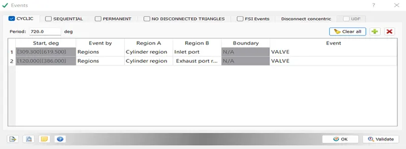
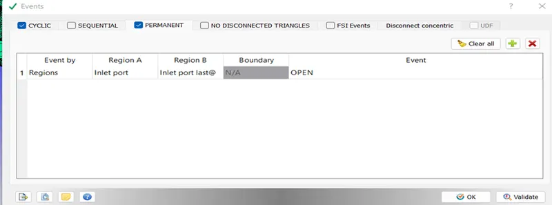
Physical models:
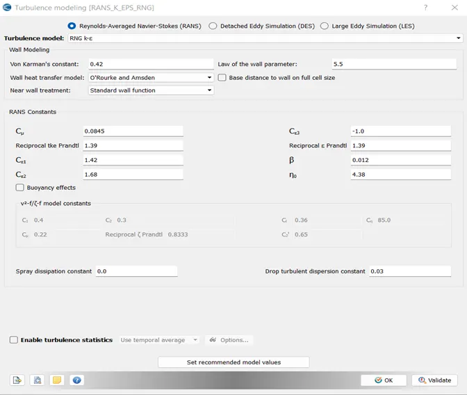
Turbulence modelling
Grid control:
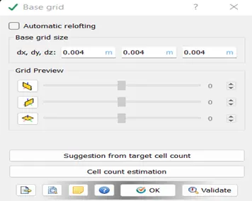
Base grid
Fixed embedding:
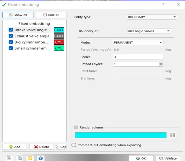
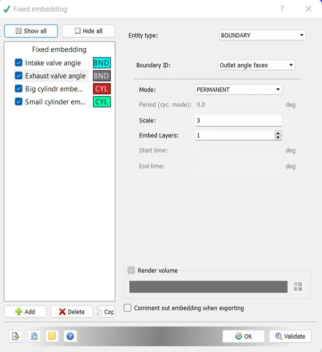
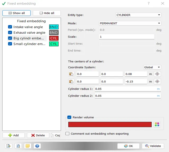
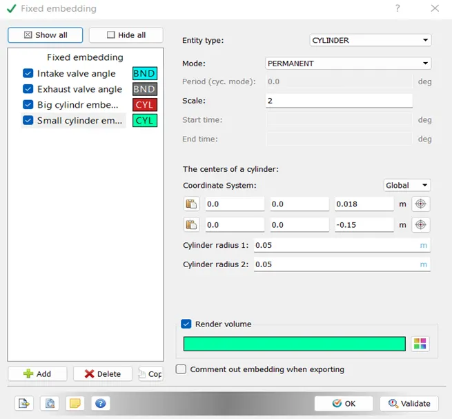
The embedding is created in different regions where the mesh should be finer.
Output/Post-processing:
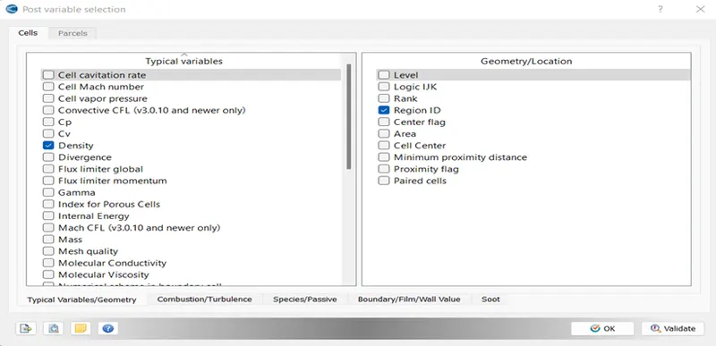
As this is No hydro simulation, so there is need to change in post variable selection.
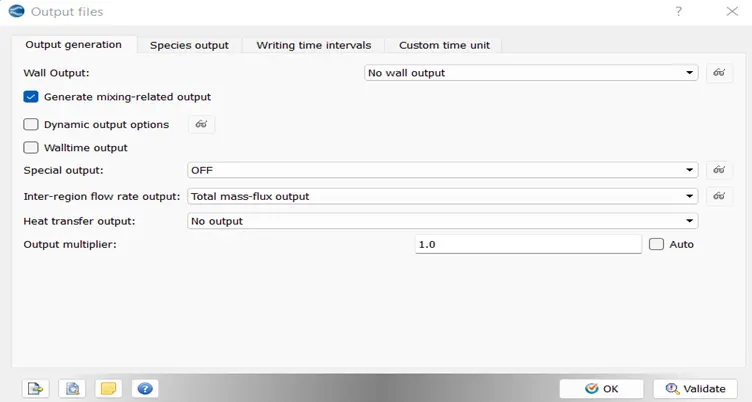
Output files: These values are set as default.
Then after case setup, the file is export to the folder created for the Port fuel injection then the simulation is to run in the Run converge option, After the simulation is done, the .out files are converted into the format where the paraview can accept for post processing
Conclusion:
This is the drive link of no hydro simulation animation
https://drive.google.com/file/d/1mZxf5BTC4VteUVTNIo7drLAB8OMCfNBh/view?usp=sharing
Transient state no hydro simulation is runned successfully. This simulation is runned to check whether the setup and mesh works correctly for the given PFI SI engine.