Week 9: Project 1 - Surface preparation and Boundary Flagging (PFI)
Introduction
the most widely produced internal combustion engines were of the Port Fuel Injected (PFI) design, where the fuel is sprayed into the intake ports to mix with incoming air. In fact, many new vehicles are still manufactured with this engine design. The fuel injectors in PFI configurations are typically mounted in the intake manifold and the air/fuel mixture is pulled into the cylinder head as the intake valve opens.
This simulation is 4stroke IC-engine
AIM
To Run No-hydro simulation in Port Fuel Injector (PFI) Engine using a design Data model
Objective
To clean up the model
Assign Boundary Condition
set the Boundary condition
Solution
Clean up model
Patching
using Repair-Patch
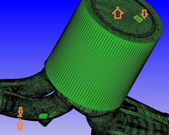
Translate
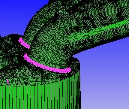
Transformation-Translate- translate normal to valve Exhaust top to 0.01mm until the error rectified
Normal
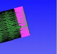
Transformation- Normal Flip normal to rectify this error
Boundary Condition
Boundary-Fence-Line (by Arc)
To create and assign name selection to the regions
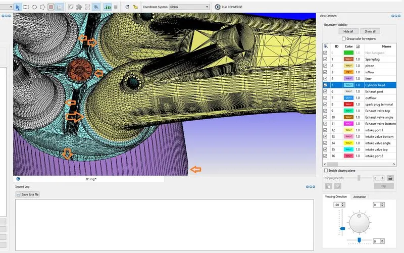
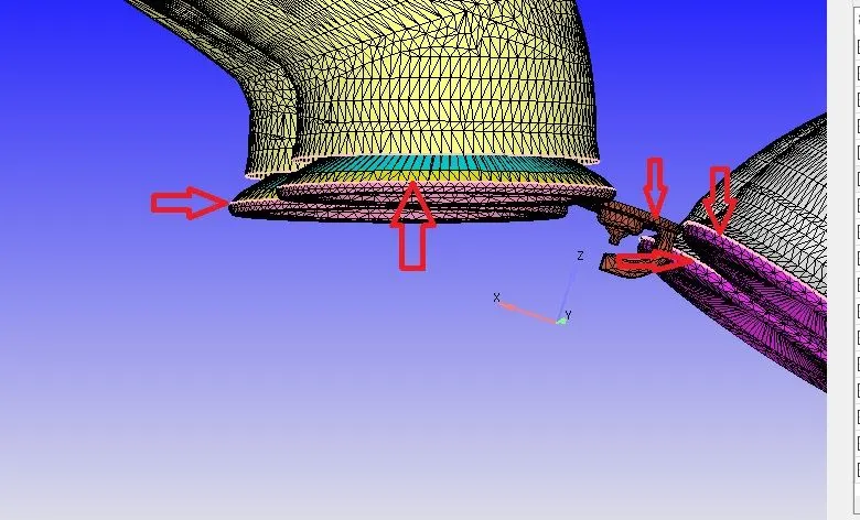
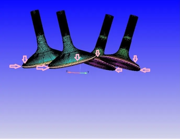
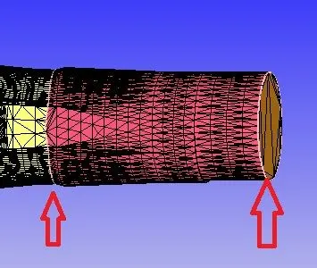
Name Selection for Boundary
Front view
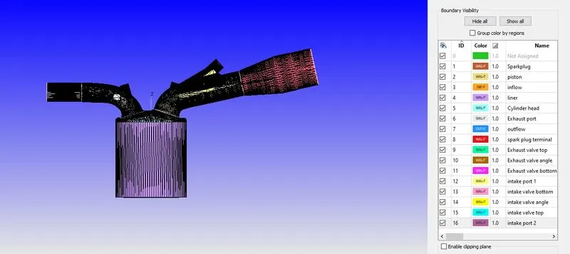
Right side View
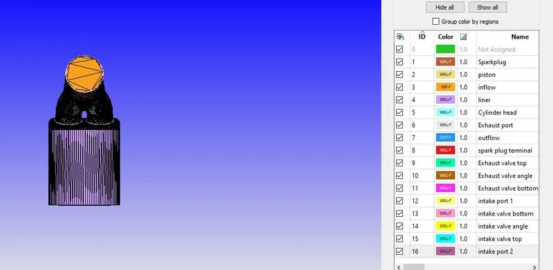
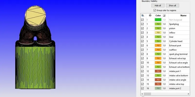
Left side view
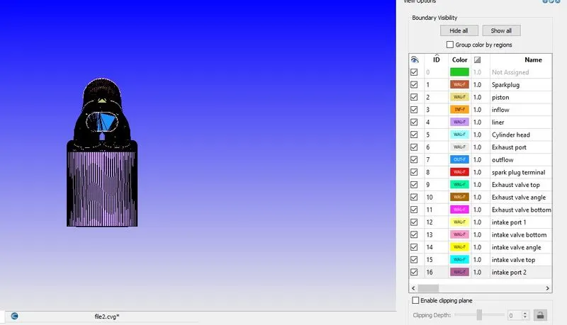
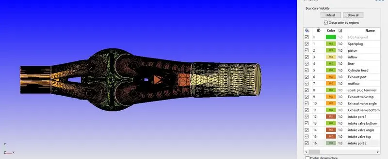
Top view
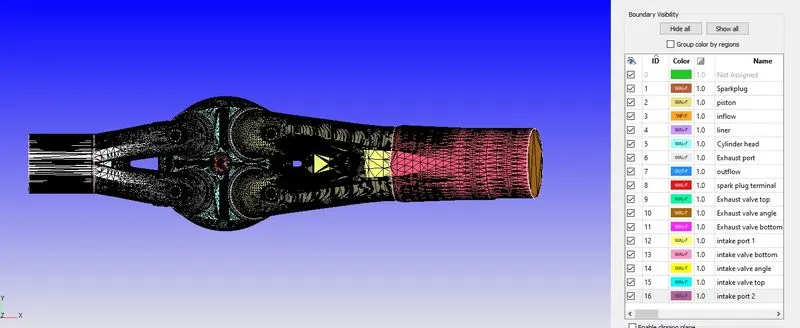
Bottom
Piston specify
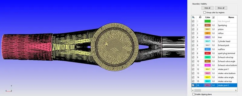
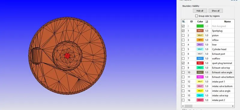
Spark plug specify with valves
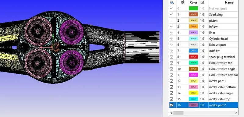
Spark Plug
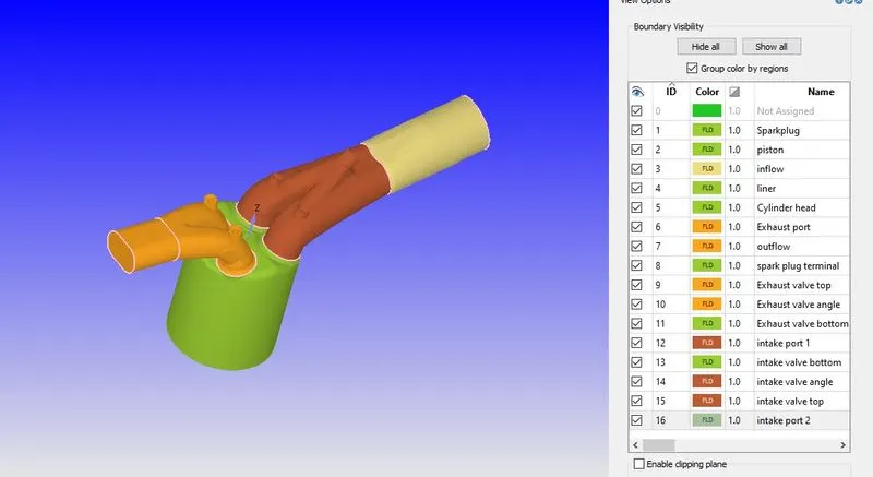
ISOMETRIC VIEW
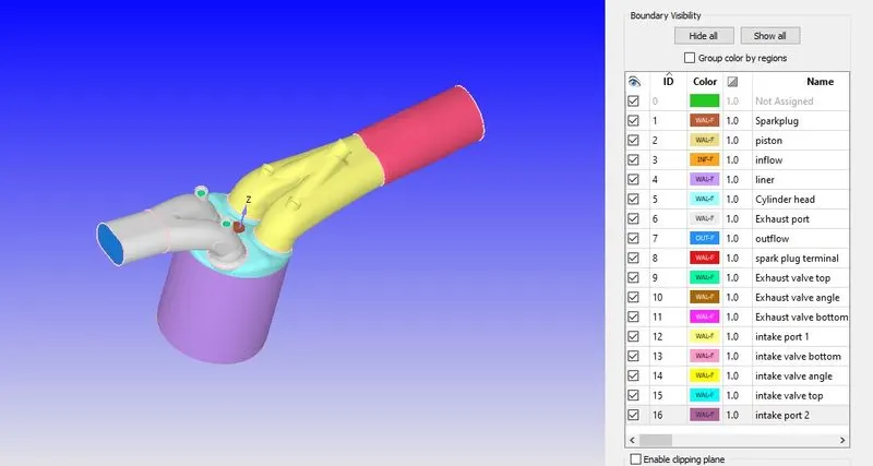
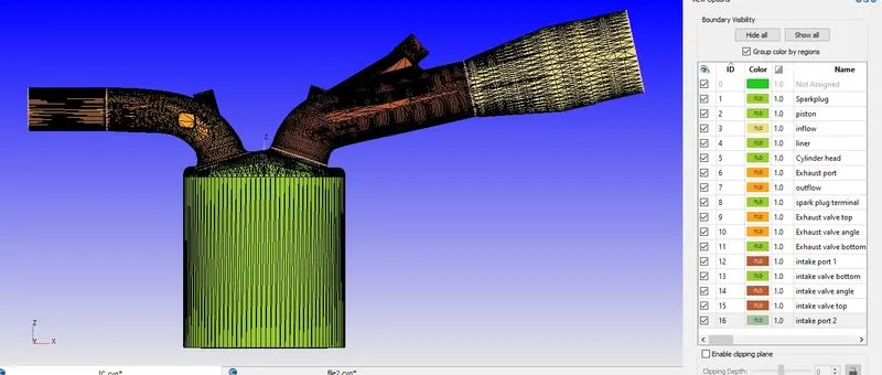
Color Represent Boundary with that name specified which mention Right side of the image
Region
Creating Region
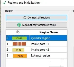
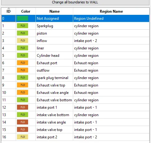
Assign Region with Boundaries
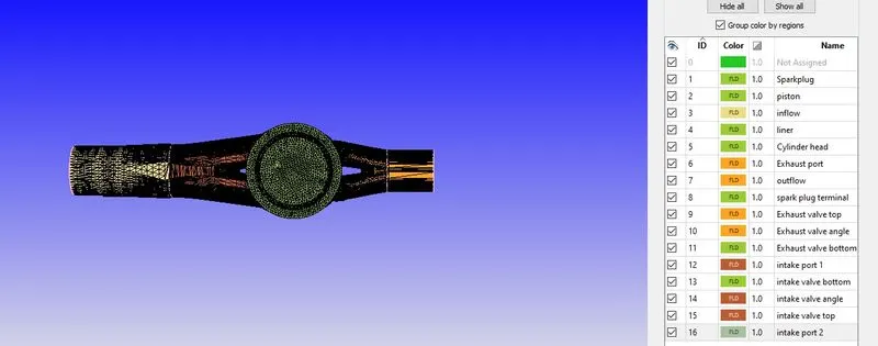
Front View
Top View
Right Side View
Left Side View
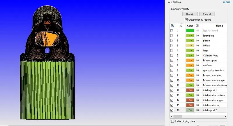
Bottom View
ISOMETRIC VIEW
Setup
Application
IC Engine
Crank Angle based
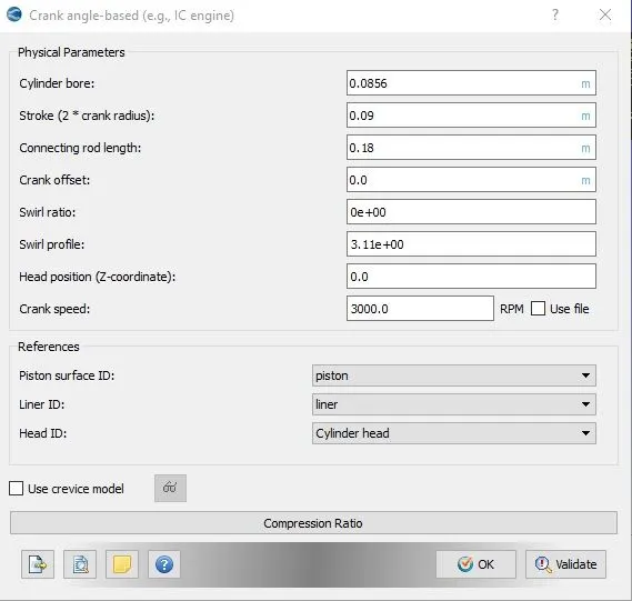
Reaction Mechanism
Import Mech.dat file
check for Reaction Mechanism
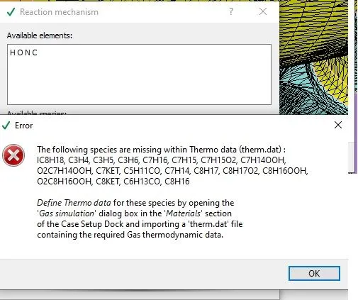
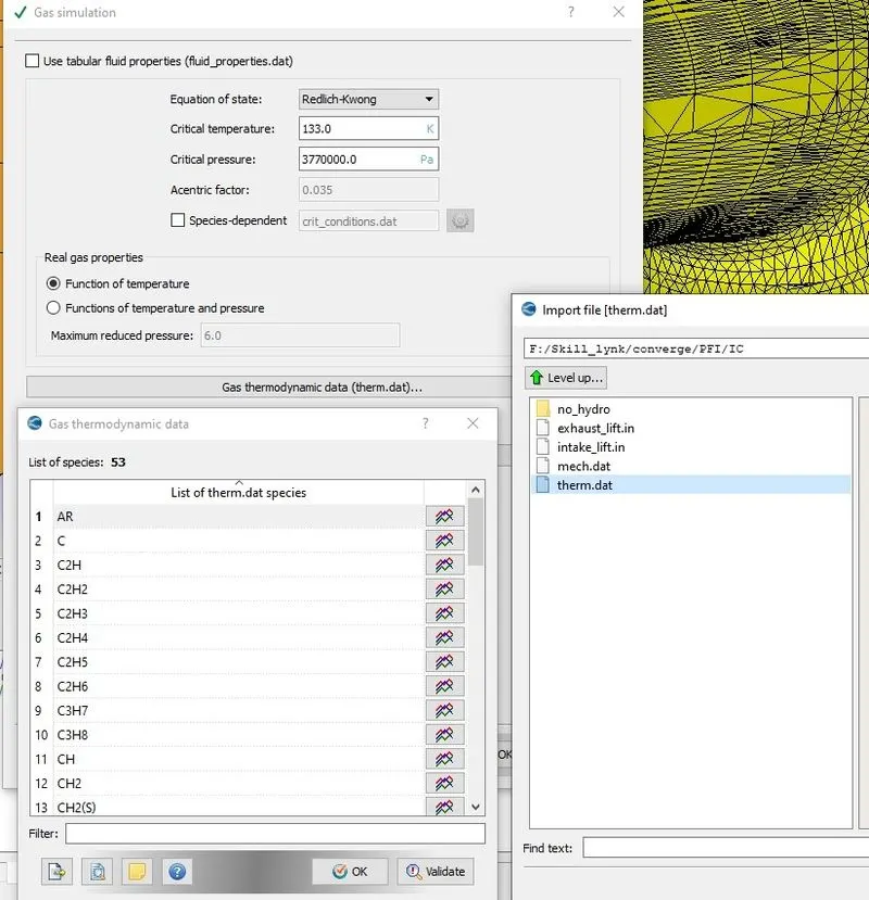
Gas Simulation
Import Thermo.dat
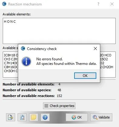
Now the error rectified in the Reaction Mechanism
check for Reaction Mechanism
Simulation Parameter
No Hydrodrodynamic solver simulation
Simulation Time Parameter
Start time: -480 deg
End time: 280 deg
above value calculated for 4 stroke Engine (720 deg)
Boundary
Spark Plug
wall-fixed
Temperature -law of wall - 550 k
Piston
moving-Translate-moving-piston
Temperature -law of wall - 450 k
inflow
Boundary type-inflow
Pressure-101325
Temperature-363
air
liner
Boundary type-wall
stationary- fixed
Temperature-450
Cylinder head
Boundary type-wall
stationary- fixed
Temperature-450
Exhaust Port
Boundary type-wall
stationary- fixed
Temperature-500
Outflow
Boundary type-wall
stationary- fixed
Pressure-101325
Species backflow
| Stoichiometric calculation | ||||
| Species | moles | MW(g/mol) | Mass | Mass Fraction |
| Co2 | 8 | 44.01 | 352.08 | 0.192304 |
| H2O | 9 | 18.01528 | 162.1375 | 0.088559 |
| N2 | 47 | 28.0134 | 1316.63 | 0.719137 |
| Total | 1830.847 | 1 | ||
bolded are species and associated mass fraction
Temperature-800
Spark plug terminal
Boundary type-wall
stationary- fixed
Temperature-600
Exhaust Valve top
Boundary type-wall
Translation- moving -User-specify-Import =Exhaust_lift.in
Temperature-525
Exhaust valve angle
Boundary type-wall
Translation- moving -User-specify-Import =Exhaust_lift.in
Temperature-525
Exhaust vale bottom
Boundary type-wall
Translation- moving -User-specify-Import =Exhaust_lift.in
Temperature-525
intake port 1
Boundary type-wall
stationary- fixed
Temperature-425
intake valve bottom
Boundary type-wall
Translation- moving -User-specify-Import =intake_lift.in
Temperature-300
intake vale angle
Boundary type-wall
Translation- moving -User-specify-Import =intake_lift.in
Temperature-300
intake valve top
Boundary type-wall
Translation- moving -User-specify-Import =intake_lift.in
Temperature-300
intake port2
Boundary type-wall
stationary- fixed
Temperature-425
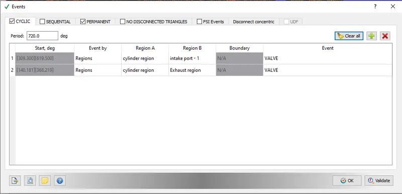
Initial Condition and Events
Cylinder Region
Pressure=101325 pa
Temperature=300 k
pull from boundary- outflow
intake port-1
Pressure=101325 pa
Temperature=390 k
Species
| Species | Mass Fraction |
| IC8H18 | 0.025508 |
| O2 | 0.20157 |
| N2 | 0.77292 |
intake port-2
Pressure=101325 pa
Temperature=370 k
species- air
Exhaust port
Pressure=1857321 pa
Temperature=1360 k
species
pull from the boundary- outflow
Events
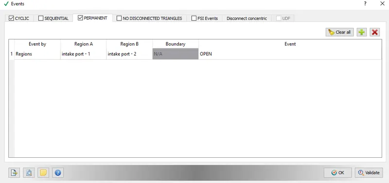
Physical model
Turbulence-RANS-k-epsilon
Grid controls
Base grid-0.004
Fixed embedding
Intake valve angle
entity type- boundary
Boundary ID- intake valve angle
mode- permanent
Scale-3
embedded layer-1
Exhaust valve angle
entity type- boundary
Boundary ID- Exhaust valve angle
mode- permanent
Scale-3
embedded layer-1
Big Scale Embedding
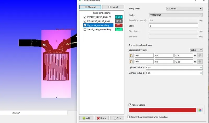
to get fine mesh in the specified region
Small Scale Embadding
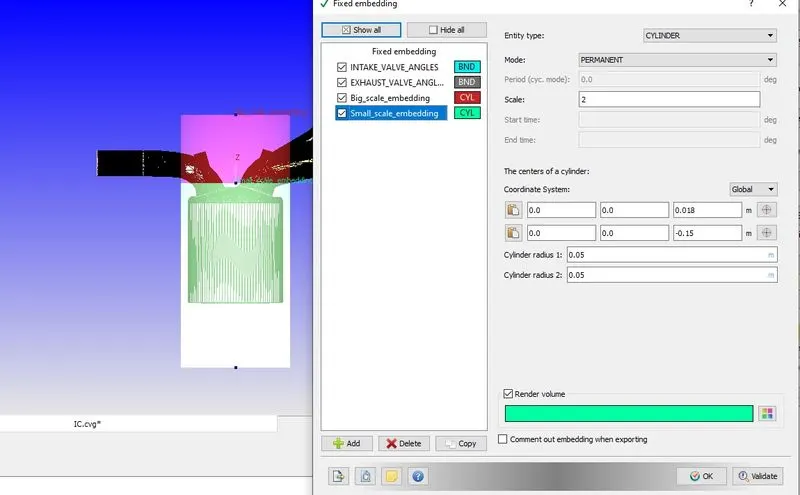
much more refined than big Scale Embedding make sure it needs to cover the entire port region to avoid errors
Finally, check any error in the geometry exporting case file
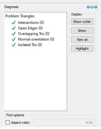
Result
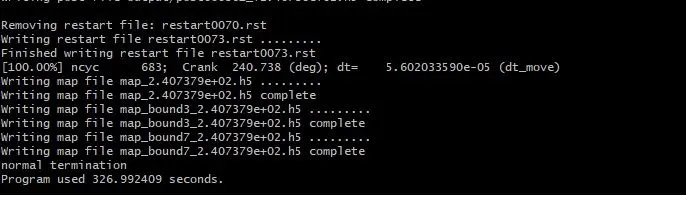
OUTPUT
RPM
Time
time in seconds
Conclusion
No hydro simulation for PFI Engine is done to check the result next is ready for analysis
Reference
https://www.aftonchemical.com/Generic/PFI-vs-GDI?__cf_chl_jschl_tk__=pmd_XfhEcBahwHPrfl8vxi_Z9W5PPaaZ_KlpFQ40BN02OzU-1635432820-0-gqNtZGzNAmWjcnBszQi9