Week 9: Project 1 - Surface preparation and Boundary Flagging (PFI)
Input geometery:
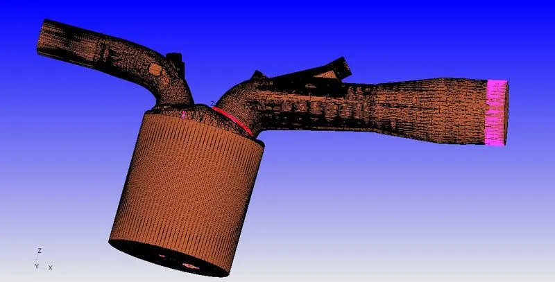
Error faced:
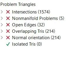
With the errors faced everthing must be cleared with one be one so that the simulation can be run. Thus to solve the geometrical errors one by one the geometry is flagged and seperated every part.
Boundary Flagging:
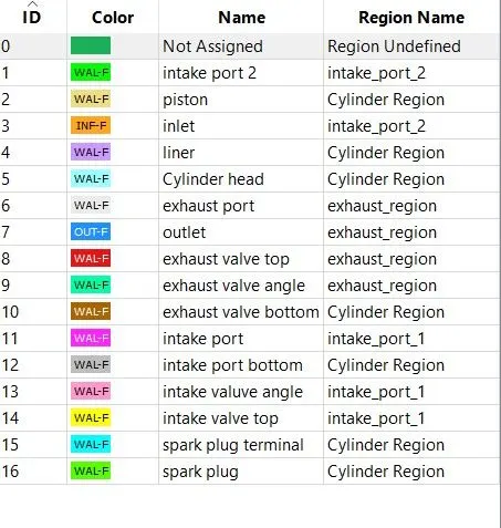
Normal error:
The Normal error is simple error where the normal of the trangles in geometry face are perpendicular to flow of fluid. Thus we have make sure all normals are towards the fluid flow and transform the normal to its position.
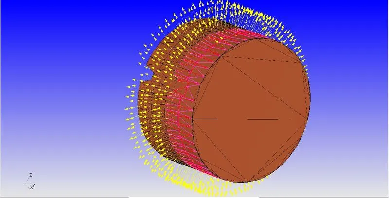
Open edges:
These open edges and closed using patch command and completed the geometry.
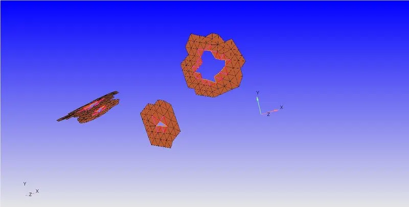
Overlapping Edges:
These are overlapping edges where the geometrical triangles overlap over the other. So these triangles are deleted and patched newly.
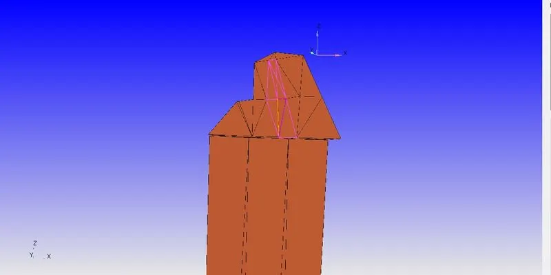
Intersection error:
In this error, the cylinder head and inlet valve are intersecting geometricaly. Thus the value is moved in a tanslating motion in its normal to avoid the intersection and create seperation between the geometry.
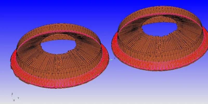
Cleared geometry(with regions):
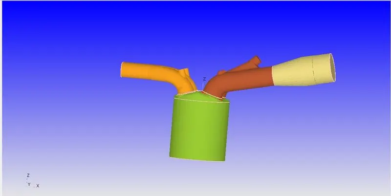
Section view of Cleared geometry(without regions):
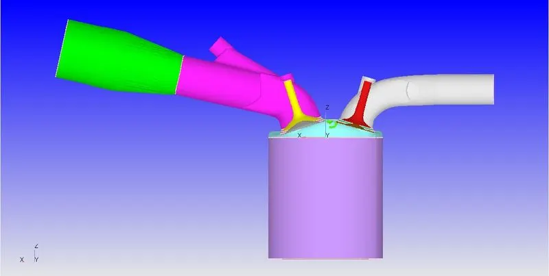
No Hydro simulation:
With the input data from the challege page, the NO hydro simulation is setup and run to study the No Hydro run of the IC engine.
Simulation application:

Gas simulation:
Thermodynamic data file is uploaded here.

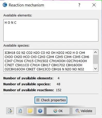
Reaction mechanism:
Mechanism file is uploaded here.
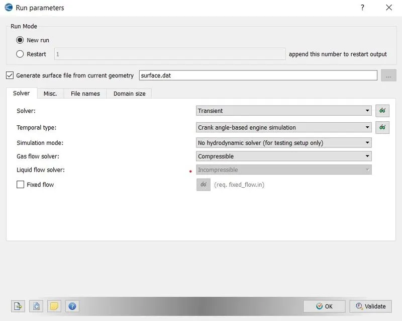
Run parameters:
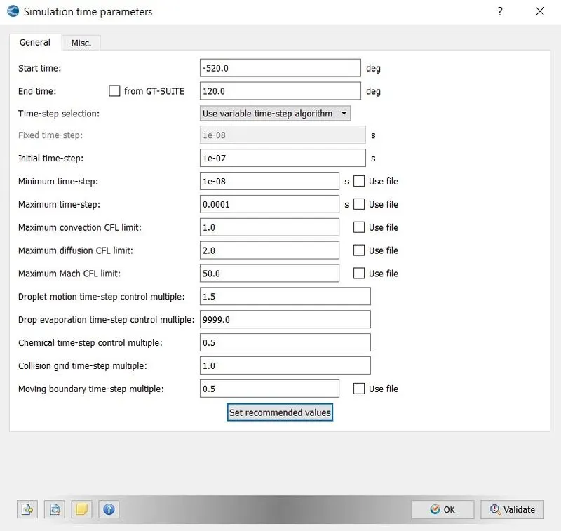
Simulation time parameters:
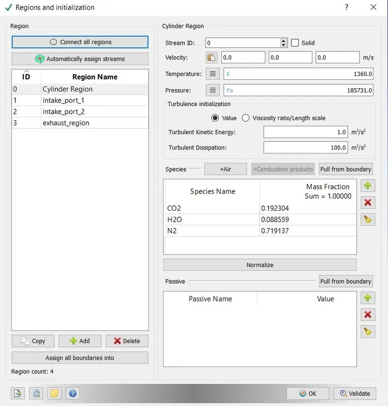
Regions:
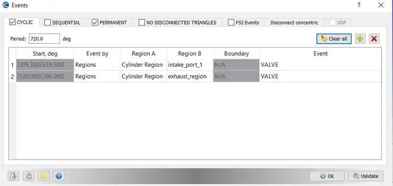
Events:
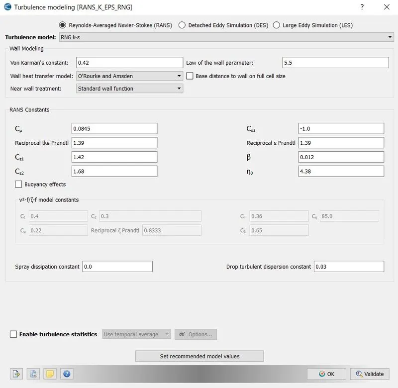
Turbulance model:
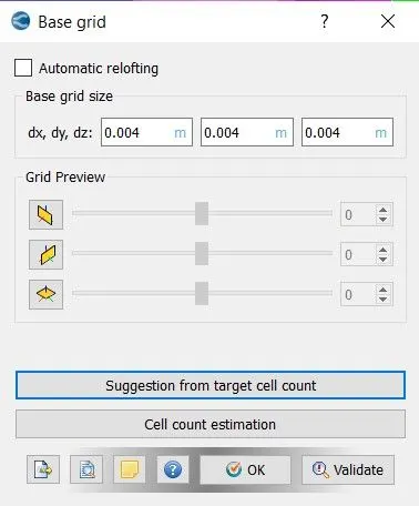
Base grid:
grid scaling = -1, changed in input files.
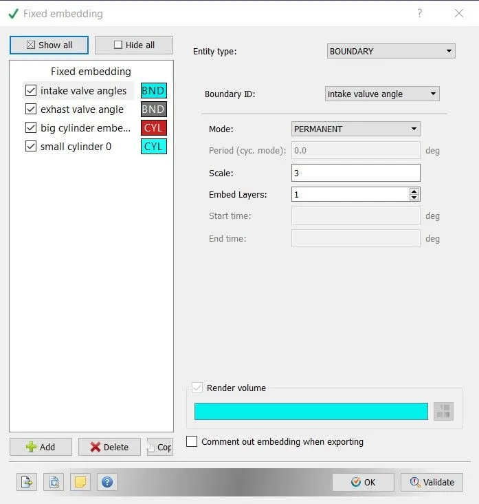
Fixed Emdding:
Results:
No hydro simulation:
Mesh Animation:
Inference:
With the input geometry and the input data, this No Hydro simulation is run. The geometry is surface prepared and boudnary flagging by clearing the errors in geometry. This shows the significance of surface preparation and boundary flagging so the simulation can be run without error with the right setup.