Week 9 - Project_1 - Door Trim Lower with Engineering Features
Class A Draft analysis
First the tooling axis is to be defined. The flat surface in the part is considered first. A point is defined in the center of the surface. The line passing through the point in x direction is constructed.
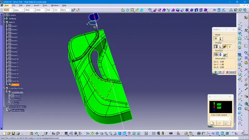
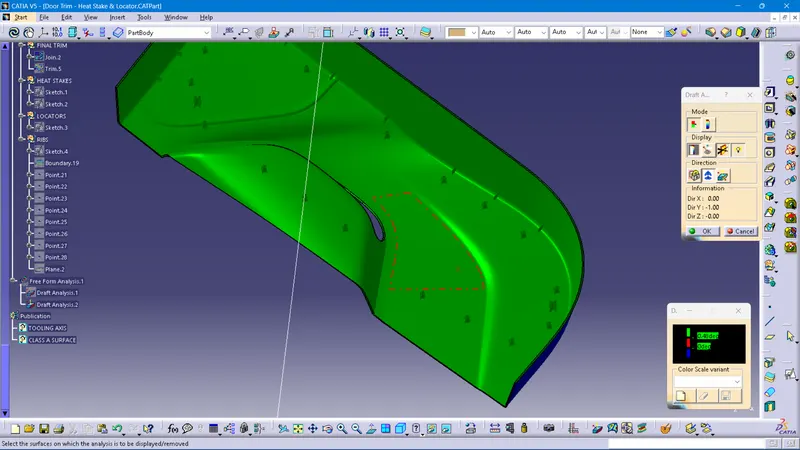
Using the above selected tooling axis, the draft analysis of class A surface is performed. Analysis result shows that all the surfaces have fairly much larger angle than 3 digree which is the nominal draft angle. The screenshots of the analysis result is given below.
To create class B surface, class A surface is offsetted by 2.5 mm which is the wall thickness of the part. Then the missing areas in the B surface is filled by tools like extract, extrapolate, trim and multisection solids.
Then C suface is created by sweeping the boundary of class A surface. And a closed surface is created by trimming class C and B surfaces and joining with class A surface.
Final Part draft analysis
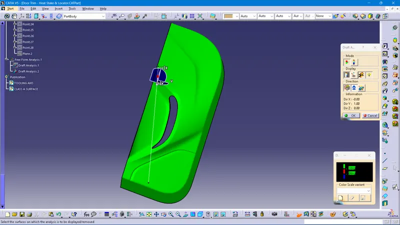
The draft analysis is conducted on the final part with tooling axis as reference. All the surfaces are greater than 3 digree which is nominal draft angle. So the part is manufacturable. But still some of the C surface is failing the analysis. The screenshots of the analysis result is given below.
Engineering Attachment Features
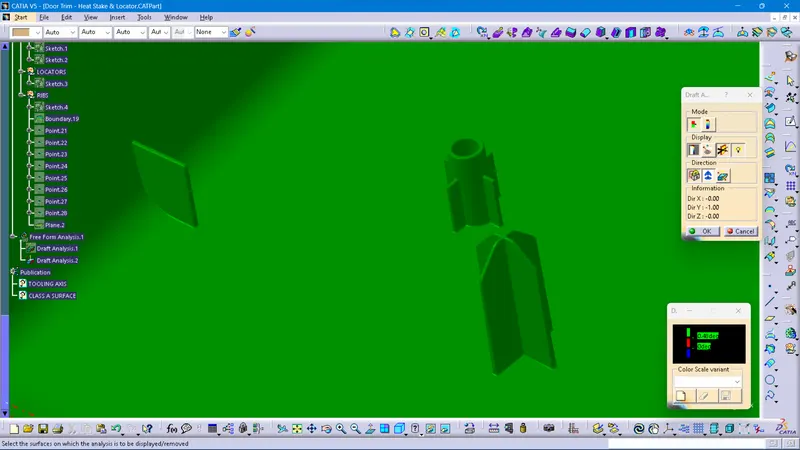
Heatstakes, ribs and locators are created in the class B surface of the part following the design rules. Thes feature are given a draft of 0.5 digrees with the tooling axis. Copy of these features are created and translated to the specified points. They are then attached to the main component.
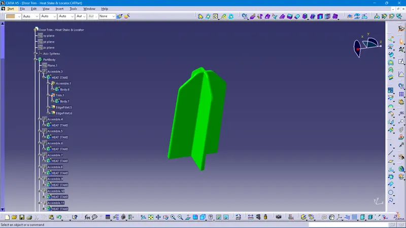
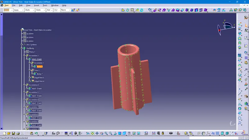
The draft analysis of these features are conducted as well. All of the features have satisfactory draft of 0.5 digrees with the tooling axis. The screenshots of the draft analysis is given below.
The CATPart is attached with the submission.