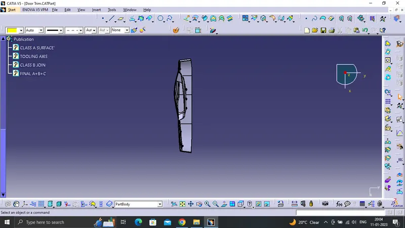
Week 9 - Project 1 - Door Trim Lower with Engineering Features
DOOR TRIM LOWER CREATION FROM GIVEN A SURFACE INPUT
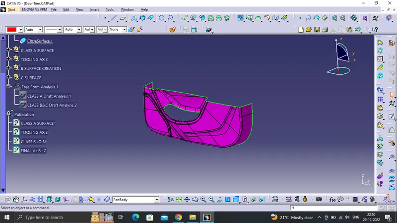
From the given surface from the input which is the A-surface. The created body should be a closed solid volume which should be easy for manufacturing and Tooling. The draft angle and draft analysis of the component should be done.
The class a surface is the outer surface which is an asthetic/styling surface which makes the component look good for the viewers perspective
TOOLING AXIS:-
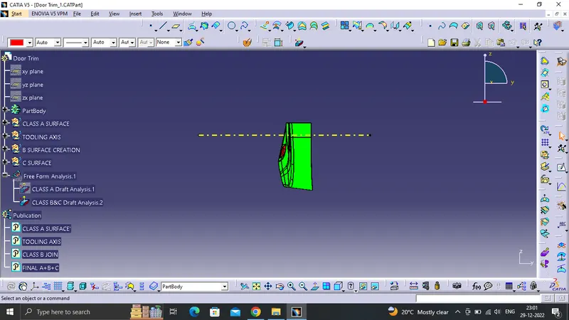
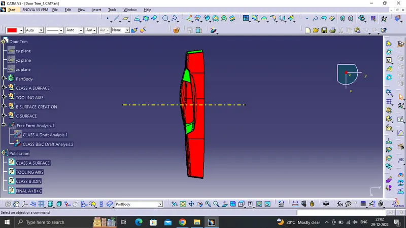
For the creation of tooling axis the component is viewed in X,Y, Z direction to check for a proper surface which can be choosen so that an easy draft analysis can be done and also which helps during the manufacturing process.
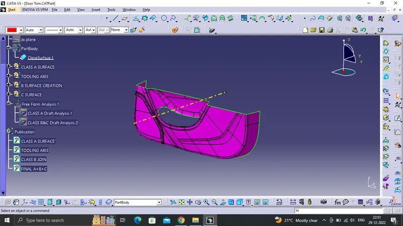
DRAFT ANALYSIS OF CLASS A SURFACE
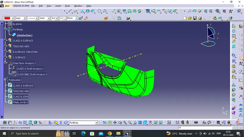
For a class A surface to be check if the surface or part can be manufactured with the required draft angle. Draft angle is needed for the component to clear the core and cavity surface as it would have shrunk towards the center while cooling.
The draft angle in majority of the designs is 3 degrees.
B SURFACE CREATION:-
For this surface the whole class A surface if offseted by 2.5mm and a B surface is obtained for us.
Once the b surface is obtained there would usually a lot of small opening/gaps present in the offset B surface which needs to be filled.
For the filling of gaps u=we use Multiple Extracts, Multi-section surface, blend, fill, extrapolate and trim commands. to obtain a sharp edge and later fillet according to the fillet values from the A-surface.
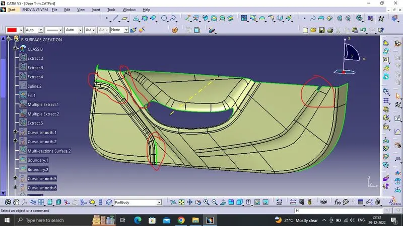
the marked sections are the areas where gaps are present these are filled and joined together.
C SURFACE CREATION :-
This surface is usually created with the help of A-Surface. The A surface boundary is extracted and sweeped across to obtain a C-Surface.
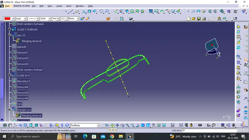
this type of boundary from the A-Surface is sweeped for usually a minimum of 5-10mm. Later this sweeped surface is joined with A-Surface using join command.
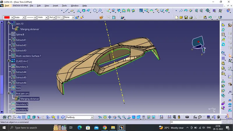
Once this surfaces are joined it is trimed with the class B-Surface.

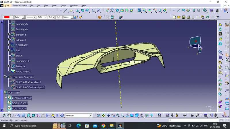
The final surface is obtained when Class A+C surface is trimmed with Class B-Surface. Now the complete body is closed to check if the body is closed. We use boundary command on the surface when applied the dialog box will display closed body can't select a boundary.
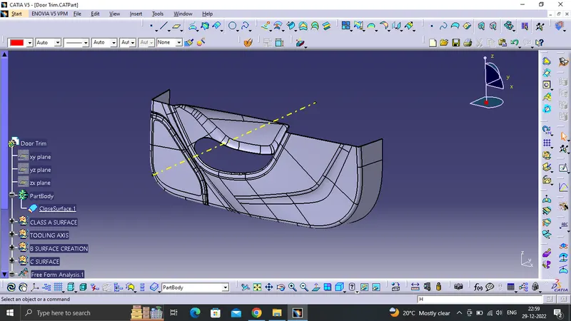
Once the surface is obtained we use Part Design Workbench to create a closed body once the closed body is applied. A draft analysis is done to check whether the draft angle is within the permisible range or not i;e 3 degrees.
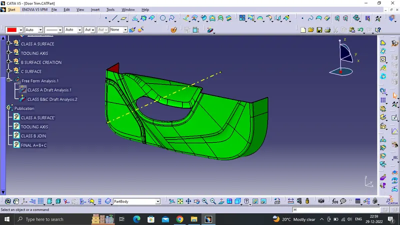
The final analysis is completed by doing draft analysis to the closed body.
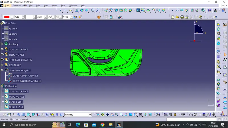
ENGINEERING FEATURES CREATION:-
- LOCATORS:- locators are meant to indicate the specific location of a component within a subassembly.
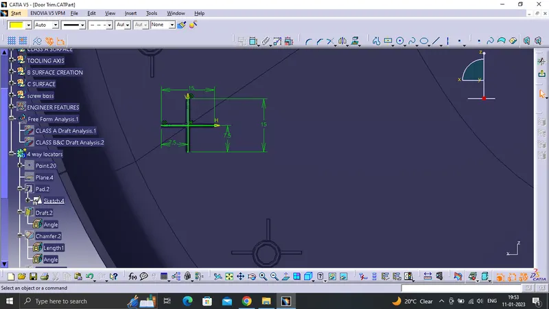
as usual a point is made on surface and a plane is created in ZX direction by using positioned sketch a sketch is created as shown above.
then PAD command is used to get a solid body since its a open sketch a solid body cannot be formed so we use thick oprtion iin PAD command.
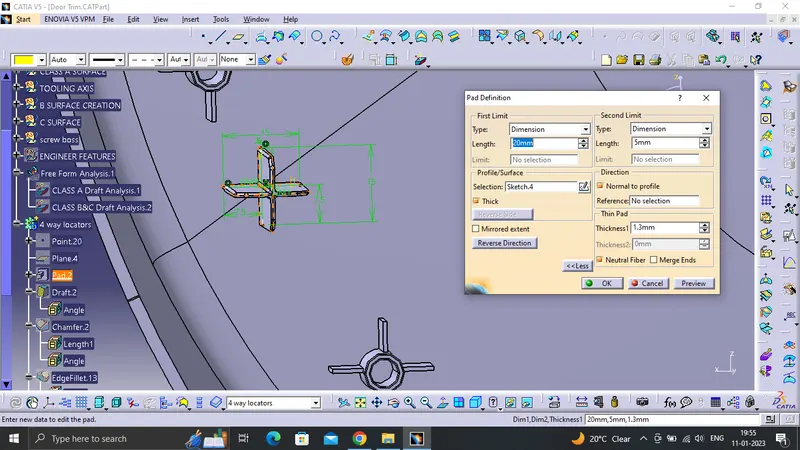
the PAD is done on both sides, later the bottom side is trimmed using union trim(Boolean operation).
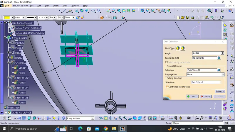
a general draft for the locator is 0.5degrees draft is done on the locator as shown.a 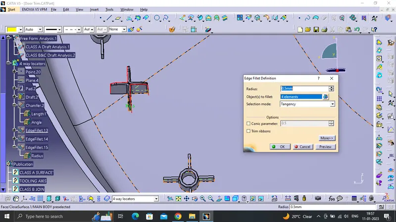
a fillet of 0.25mm is given on all sides as per the design rules.
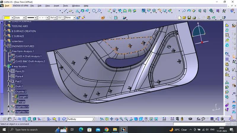
all the required engineering features are created .
DIFFERNET VIEWS:-
- ISOMETRIC VIEW:-
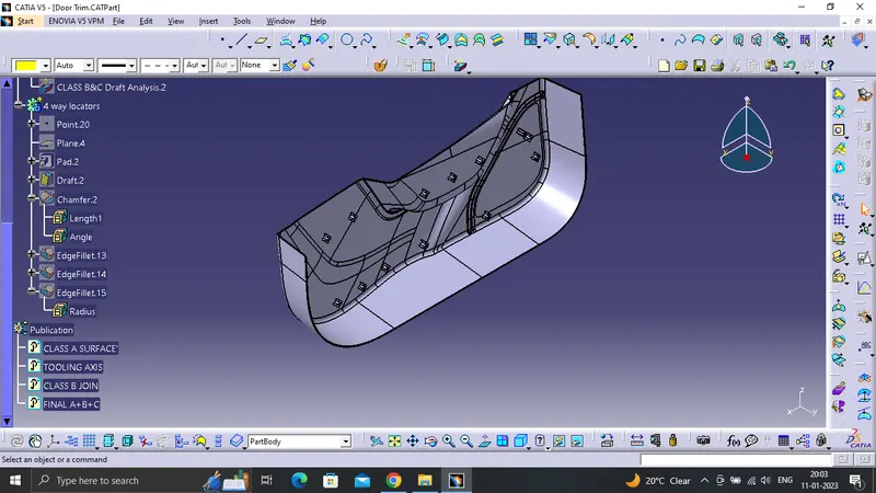
- SIDE VIEW:-
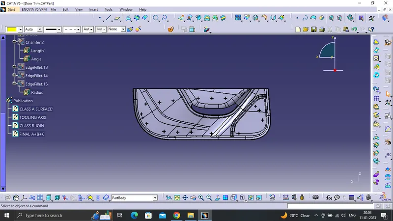
- TOP VIEW:-