Week 9 - Project 1 - Door Trim Lower with Engineering Features
Create the Door Trim Lower Plastic component through the given Class-A surface. To begin with, the tooling axis for the given Class-A Surface should be created meeting the requirements of the draft angle and at the end perform the Draft analysis on the model.
Create the Heat Stakes and the locators considering the design rules mentioned in the video for the door applique.
NOTE:
- Sketches
- Use Positioned sketch
- Sketches should be Iso-Constrained
- References
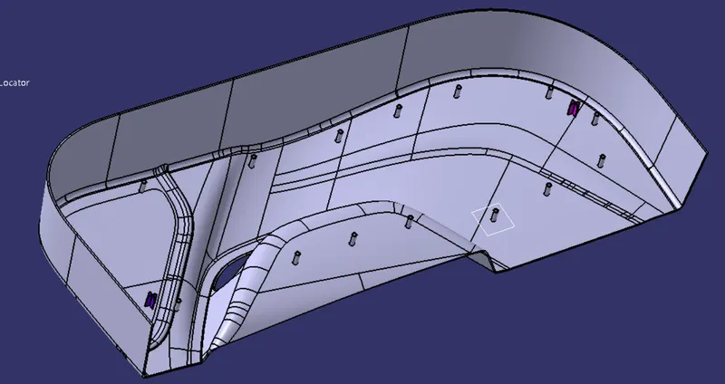
- Use the given points in the model to create the locators and Heat stakes
- Refer to the below-given image for more details
- Tree Structure
- Ensure Proper Tree Structure
- Geometrical sets should have a proper name based on the sketches present inside of it
- All the sketches should be created under the Geometrical set
- Report
- A detailed report should be done explaining the draft analysis and the tooling axis creation.
- An explanation should be given on the way of creating the tooling axis, particularly the Bisecting method.
AIM:
To create Plastic design and attach the Engineering features and generate the Draft Analysis for the given Door Applique Class A model.
PROCEDURE:
Check for any openings in the given model Door Applique by using BOUNDARY. In BOUNDARY > select edges - select the surface to create the boundary at the openings.
Create a point at the center of the surface by using Point Definition by : Point Type - on surface ,Surface - select the surface and Distance - 0
By using the Line Definition option create a line in Y direction by : Line Type - Point-Direction, Point - select the point and Direction - Y which will be the Main Tooling Axis(Yellow).
Do the draft analysis on Class A surface.
CREATING B-SURFACE FOR DOOR APPLIQUE:
Extract the Class A surfaces by selecting the surface to extract and Untrim the surfaces by selecting the surfaces which are required and offset the untrimmed surfaces by selecting the surfaces to offset to a distance of 2.5mm and then trim the surfaces.
Fillet the surface with a radius and extrapolate the surface.
CREATING C-SURFACE FOR DOOR APPLIQUE:
Extract the Boundary of Class A by Extract option and Using Sweep option create the Class C surface.
Smooth curve the extracted boundary and then in Sweep option : Type - With draft direction , Guide Curve - Boundary and Draft direction - Tooling axis and angle as 3 degrees.
Create the C surface for 2 boundaries separately.
After creating the C surface,join the Class A and Class C surface by Join option and then trim it with the B surface.
In Part Design,fill the surface body with the solid using Close surface.
ADDING LOCATORS(4 WAYand 2 WAY) TO DOOR APPLIQUE:
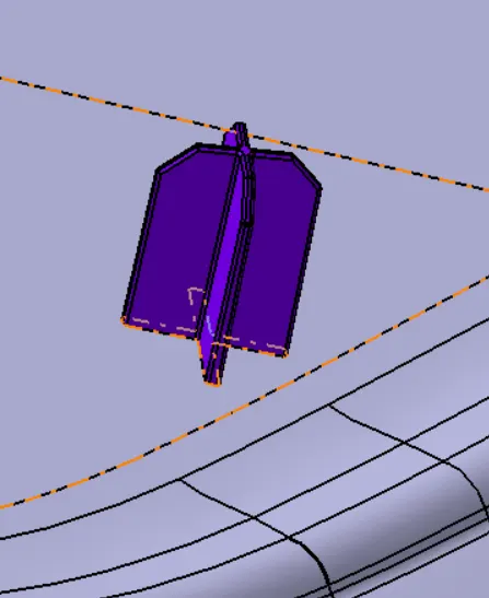
Create a point at the center of the surface of Door Attachment by Point Definition.
Create a plane on the surface at the center by Plane Definition with reference to the Point which was created and then create a sketch of a 4 way locator on the plane.
ADDING HEAT STAKES TO DOOR APPLIQUE:
Offset the Class A surface to 2.5mm and extract the boundaries of the offsetted surface.
Parallel Curve the extracted boundaries by Parallel Curve Definition : Curve - extracted boundary, Support - surface , Constant - distance.
Give the Points Repetition to the Parallel curves by Points and Planes Repetition by : Curve - Parallel curve, Parameters - Instances and Instances - no of points.NO Heat stakes should present nearer to Locators.
Now create a sketch on the point created on a Parallel curve.Draw the circles with diameters of 5mm and 7mm and in Part Design,Pad it : Type - to surface , Limit - select the Class A surface.