Week 9 - Project 1 - Door Trim Lower with Engineering Features
Door Trim Lower with Engineering Features design heat stakes and the locator's design considering the design rules
AIM:
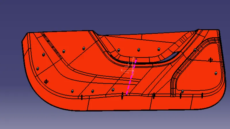
Create the Door Trim Lower Plastic component through the given Class-A surface. To begin with, the tooling axis for the given Class-A Surface should be created meeting the draft angle requirements and performing the draft analysis on the model at the end.
Design the Heat Stakes and the locators considering the design rules.
Class A surface:
This is the styling surface that provides the aesthetic features of a component. A designer starts the design of component by given class A surface.
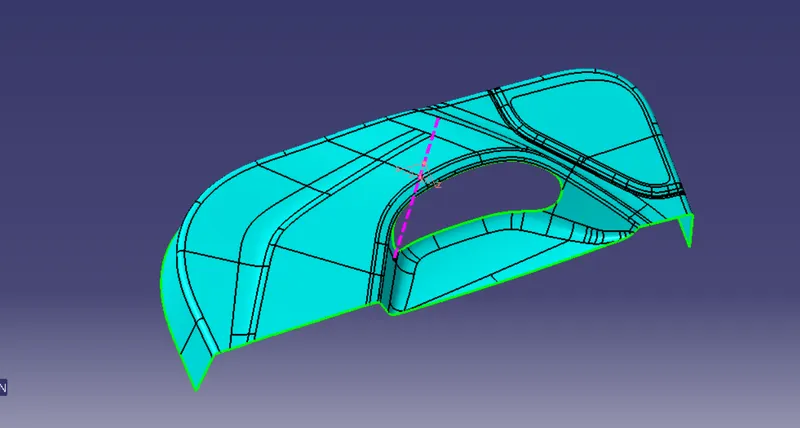
TOOLING AXIS CREATION
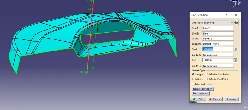
Tooling direction has to be the direction in which most of the features can be easily cleared. To create the tooling axis first we have to check the best suitable direction for tooling by using the compass. the y direction is suitable for creating the tolling axis because in the y direction most of the surfaces are clearing while performing draft analysis. Generally tooling axis is created using bisecting line method but here A line normal to the surface is created in the y direction and considered the tooling axis.
In injection molding, the Class A surface is first analyzed to determine the axis or tooling direction that separates the molds. Tooling direction is critical for plastic product design because it determines mold direction.
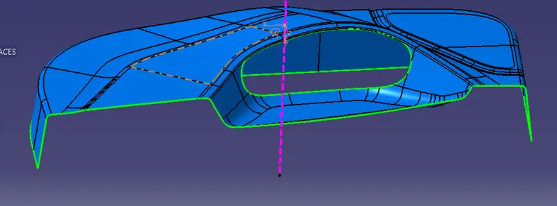
CLASS B SURFACE
To create a class B surface class A surface is offset to 2.5mm and we have to work on the patches by using the multisection or sweep features if required 2.5mm is the thickness of the component
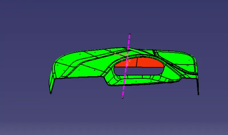
DRAFT ANALYSIS OF THE FINAL COMPONENT
Draft analysis is an operation that is performed to know the draft angles of the surfaces concerning the tooling direction.
The minimum feasible draft angle for this design is 3 degrees. Generally for plastic components, a minimum draft angle that can be achieved is 0.5 degrees
- Go to the Insert menu and select the Analysis option.
- Select Feature Draft Analysis.
- Select the Material option and select the surface.
- Drag the compass and place it on the tooling axis.
- click on the surface and see that the surface is within the permissible limit of the draft values.
- Click on Okay.
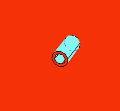
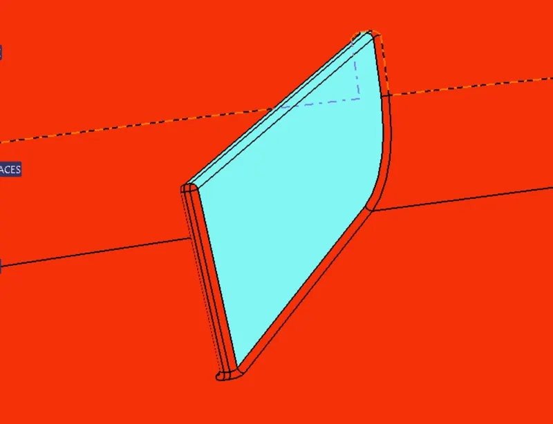
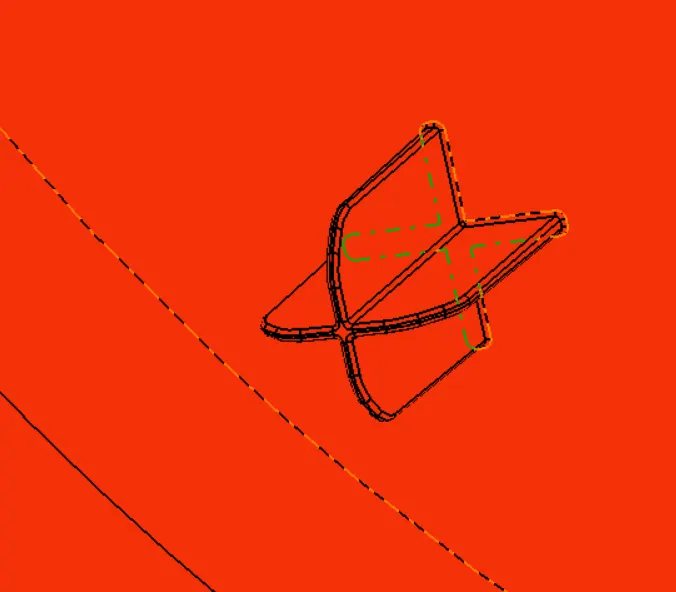
FINAL IMAGES OF HEAT STAKES AND LOCATORS :