Week 9 - Project 1 - Door Trim Lower with Engineering Features
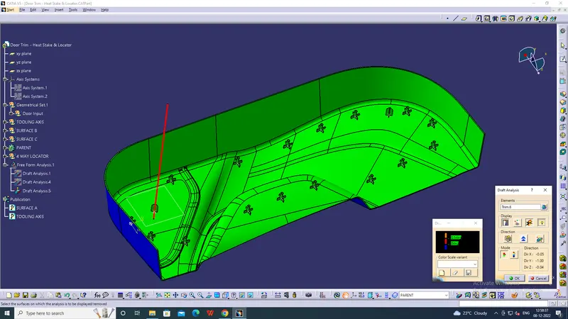
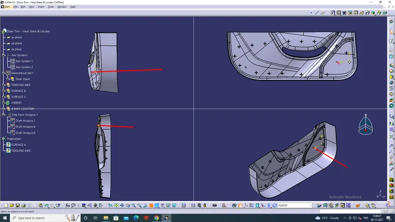
COMPLETE DRAFT ANALYSIS
DOOR TRIM
WEEK 8 CHALLENGE 5
AKASH PATIL
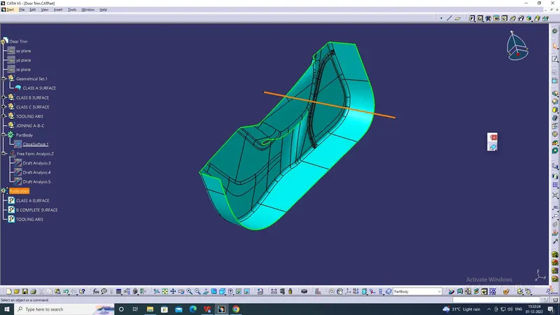
- TOOLING AXIS
Tooling axis is the axis along which the mold (core and cavity) opens/moves. And with
respect to which the draft angle is given.
- STEPS TO CREATE TOOLING AXIS
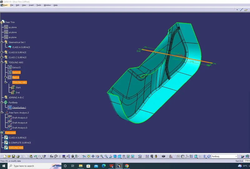
Analyse the CLASS A surface , if there if any flat surface then create the tooling axis
perpendicular to that surface.
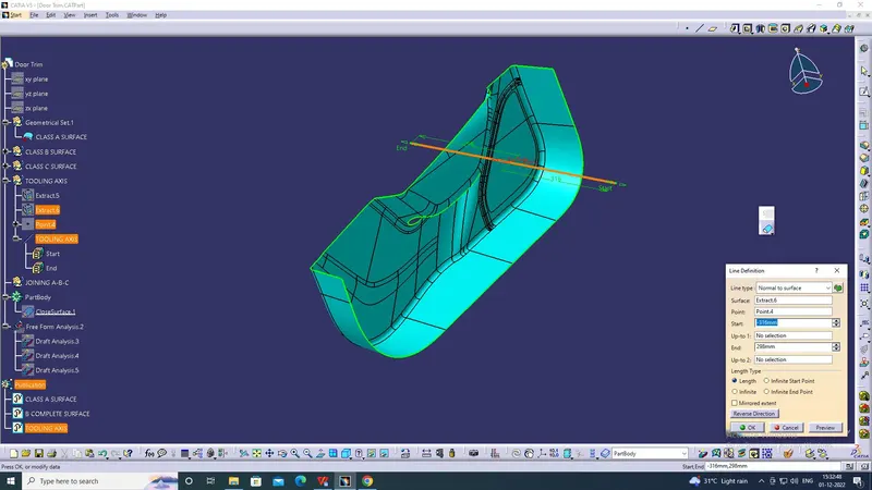
Here in this design we have one flat surface , then with help of point and line command ,
tooling axis is created, as shown in below pictures.
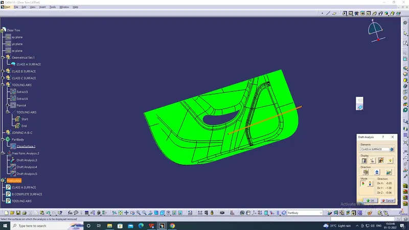
3. ABOUT DRAFT ANALYSIS AND WHY IS IT REQUIRED
The draft analysis technique is used to analyze whether our part model created in CAD
is manufacturable based on the draft condition applied.
It is required to do draft analysis to ensure whether with respect to the determined
tooling axis the part will be ejected with getting damaged .
- ABOUT CLASS A SURFACE
Class ‘A’ surfaces are primarily used in the automotive environment and refer to those
surfaces which are visible in a product. In other words. A - class surfaces are those
aesthetic/free-form surfaces, which are visible to us (interior/exterior), and have an
optimal aesthetic shape and high surface quality.
- DRAFT ANALYSIS OF CLASS A SURFACE
- ABOUT CLASS B SURFACE
Class B surface is the thickened surface from class A which consist of ribs, dog house
and other engg. features for respective purpose.
- CREATION OF CLASS B SURFACE
To create class B surface, we have to first extract all flat surfaces, excluding fillet edges.
Then untrim the extracted surfaces and extrapolate them with point continuity
Trim the surface as required and the give fillet edge with value (R+thickness).8. ABOUT CLASS C SURFACE
The surface joining surface A & B is called as class C surface.
- CREATION OF CLASS C SURFACE
Create boundary on class A surface as complete one or in separate parts depending on
part geometry
Then under SWEEP command, WITH LINES, WITH DRAFT DIRECTION select the
boundary as profile and tooling axis as draft direction , we get surface C
- FINAL SOLID BODY DRAFT ANALYSIS
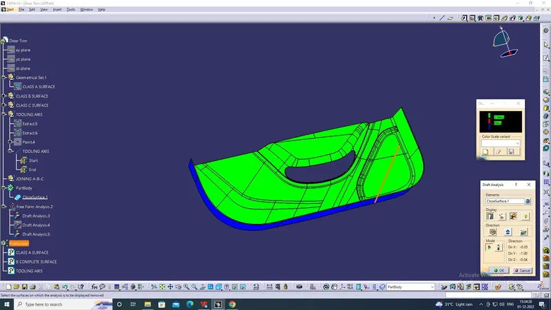
11.JUSTIFICATION OF MANUFACTURING.
THROUGH THE DRAFT ANLYSIS WE CAN SAY THAT ALL THE SURFACE HAVE MINIMUM OF 3 DEGREE
DRAFT WITH RESPECT TO THE TOOLING AXIS AND PART WILL BE EJECTABLE FROM MOLD.