Week 8 - Challenge 4 - Bumper
BUMPER DESIGN
WEEK 8 CHALLENGE 4
AKASH PATIL
- TOOLING AXIS
- Tooling axis is the axis along which the mold (core and cavity) opens/moves. And with respect to which the draft angle is given.
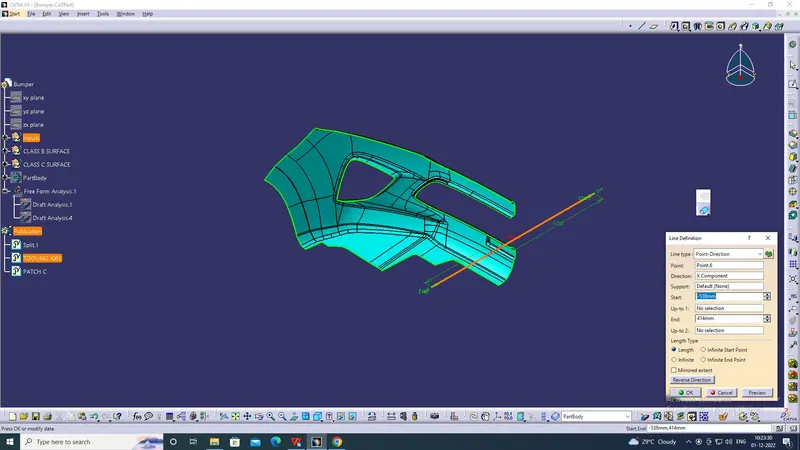
- STEPS TO CREATE TOOLING AXIS
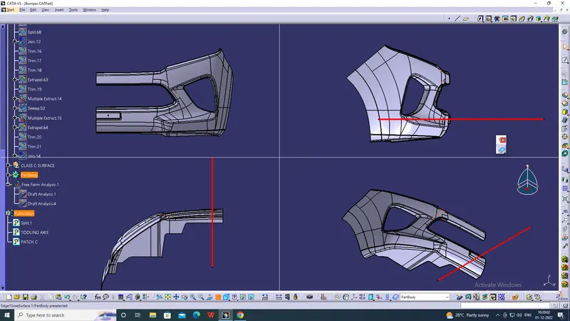
- Analyse the CLASS A surface , if there if any flat surface then create the tooling axis perpendicular to that surface.
- Here in this design we have one flat surface , then with help of point and line command , tooling axis is created, as shown in below pictures.
- ABOUT DRAFT ANALYSIS AND WHY IS IT REQUIRED
- The draft analysis technique is used to analyze whether our part model created in CAD is manufacturable based on the draft condition applied.
- It is required to do draft analysis to ensure whether with respect to the determined tooling axis the part will be ejected with getting damaged .
- ABOUT CLASS A SURFACE
- Class ‘A’ surfaces are primarily used in the automotive environment and refer to those surfaces which are visible in a product. In other words.A - class surfaces are those aesthetic/free-form surfaces, which are visible to us (interior/exterior), and have an optimal aesthetic shape and high surface quality.
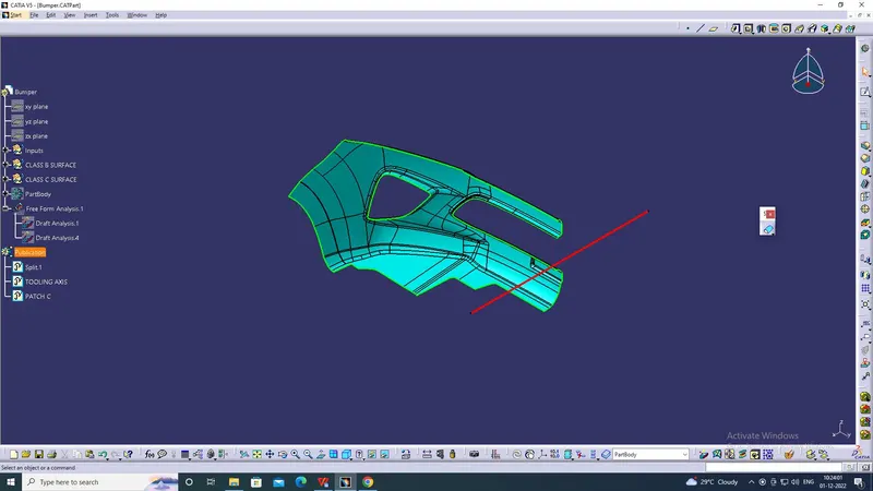
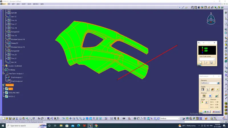
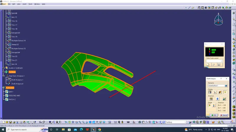
- DRAFT ANALYSIS OF CLASS A SURFACE

- ABOUT CLASS B SURFACE
- Class B surface is the thickened surface from class A which consist of ribs, dog house and other engg. features for respective purpose.
- CREATION OF CLASS B SURFACE
- To create class B surface, we have to first extract all flat surfaces, excluding fillet edges.
- Then untrim the extracted surfaces and extrapolate them with point continuity
- Trim the surface as required and the give fillet edge with value (R+thickness).
- ABOUT CLASS C SURFACE
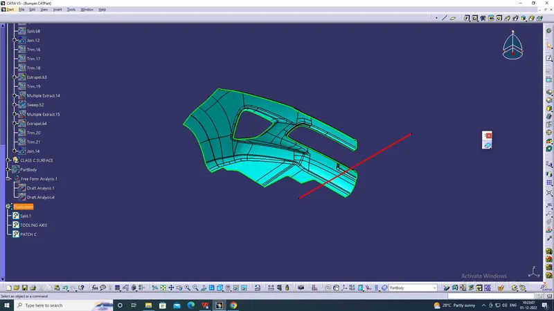
- The surface joining surface A & B is called as class C surface.
- CREATION OF CLASS C SURFACE
- Create boundary on class A surface as complete one or in separate parts depending on part geometry
- Then under SWEEP command, WITH LINES, WITH DRAFT DIRECTION select the boundary as profile and tooling axis as draft direction , we get surface C
- FINAL SOLID BODY DRAFT ANALYSIS
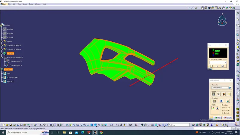
- JUSTIFICATION OF MANUFACTURING.
- THROUGH THE DRAFT ANLYSIS WE CAN SAY THAT ALL THE SURFACE HAVE MINIMUM OF 3 DEGREE DRAFT WITH RESPECT TO THE TOOLING AXIS AND PART WILL BE EJECTABLE FROM MOLD.