Week 9 - Project 1 - Door Trim Lower with Engineering Features
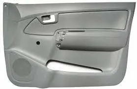
AIM : Create the Door Trim Lower Plastic component through the given Class-A surface. To begin with, the tooling axis for the given Class-A Surface should be created meeting the requirements of the draft angle and at the end perform the Draft analysis on the model.

OBJECTIVE
- To design Door trim as per automotive industry Standard.
- Create tooling axis for the given CLASS-A surface.
- Create B Class and C Class surfaces
- Create final surface model and convert it into solid body using close surface command in the part design workbench.
- Perform draft analysis for both Class-A surface and Final part body.
Material : most modern automobiles have been made of a combination of polycarbonate called PC (light weight, Durability. Polycarbonate is 250 times stronger than glass )
DESIGN METHODOLOGY
Skin data would be provided to us by the styling team to us.
Class-A surface means visible surface. It gives the aesthetic of the component which is created by the styling team and gives to the part design engineer to create the part with all engineering aspects.
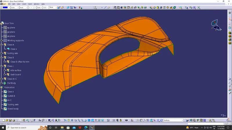
The first step is to check the continuity of the class A surface. This is to ensure that there is no gap between surfaces. If we find any then we should fix that first.
Class-A continuity check
Analyse the class A surface through visual inspection.
To make sure that the given surface has no gap in between them. We can check it also with the help of Join or boundary commands
Procedure for creating the tooling axis
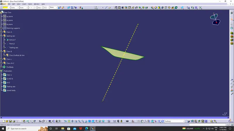
Tooling axis represents the opening and closing of the mold core and cavity during the manufacturing of the components. A plastic product designer should consider the best tooling direction to cutdown the cost of the component very less.
Method opted for creating tooling axis for the bumper
- Check the best tooling direction for the given surface.
- We can find out the best tooling direction by cross checking all the three axes.
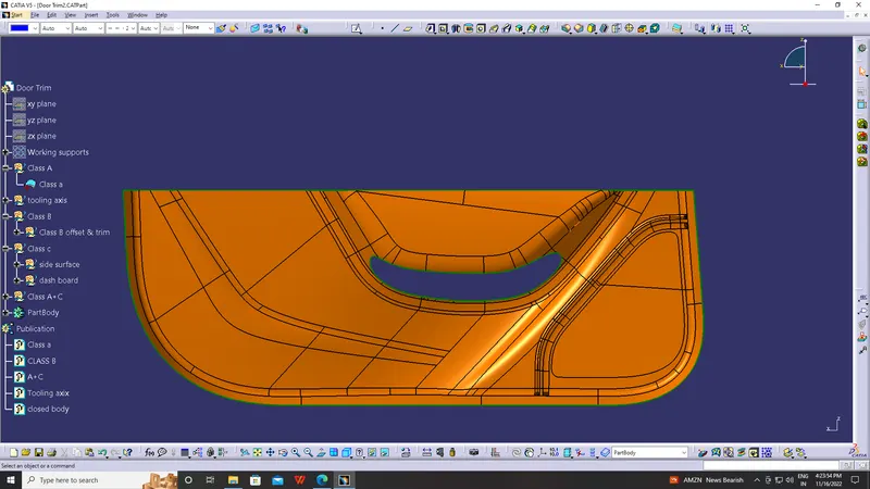
Draft analysis for the given CLASS-A surface
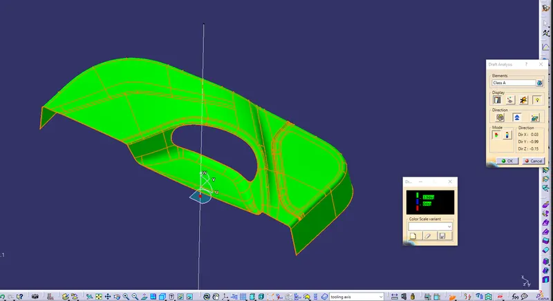
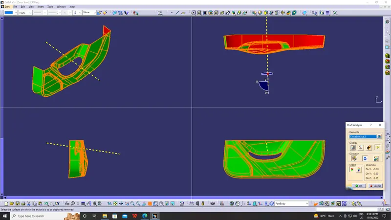
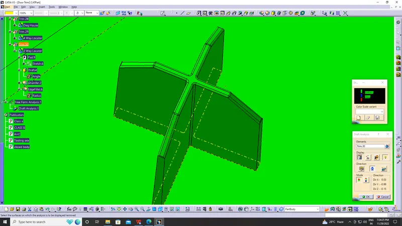
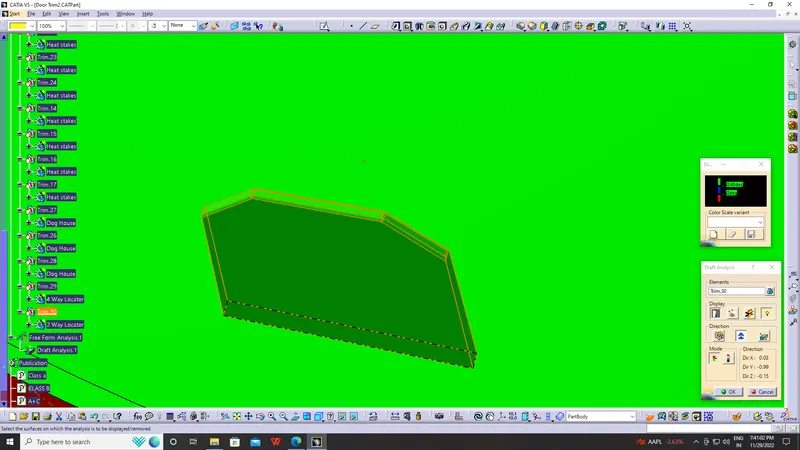
The Draft Analysis is a command enables you to detect if the part you drafted will be easily removed. This type of analysis is performed based on colour ranges identifying zones on the analysed element where the deviation from the draft direction at any point, corresponds to specified values.
Draft analysis is done after determining the tooling axis, draft analysis is used to check whether the minimum draft (3 degrees) is maintained or not.
- Procedure for performing the draft analysis are as follows
- Change the view mode of the component to be in customized parameter mode and then select the shading mode as materials.
- Then open the featured draft analysis tool from the insert menu.
- Then click on use the compass to define the current drafting direction and then drag and align the compass on the Tooling axis.
- Then lock the draft direction and perform draft analysis by clicking on the component.
- The green colour shows the positive daft tooling direction and the given surface passes the draft analysis.
- Click on the analyses under the running point to check the draft analysis on the individual faces. It shows how much draft on specific points when we move the cursor point.
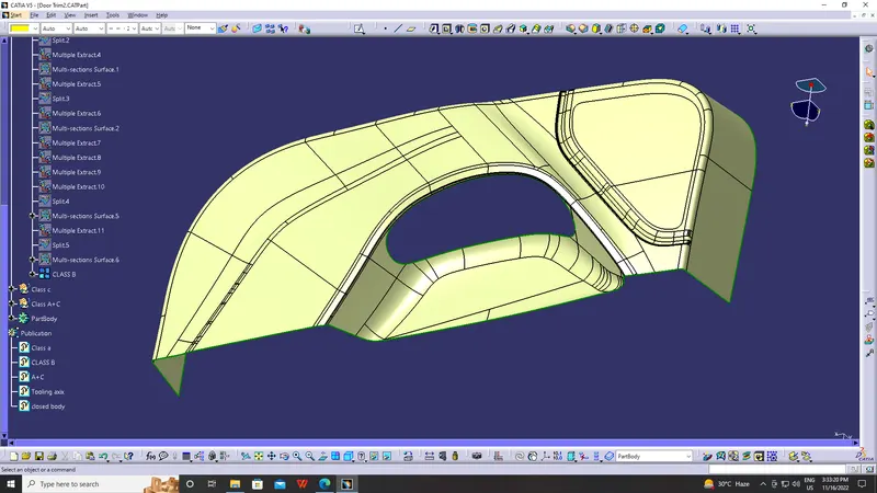
Class-B surface means thickness of a part it is not visible and is inside part. In other words, Class-B surface is a surface below a certain thickness from the class-A surface. This is the surface that contains engineering aspects of a model.
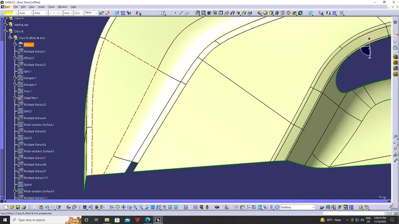
- Offset the class-A surface to 2.5 inward direction.
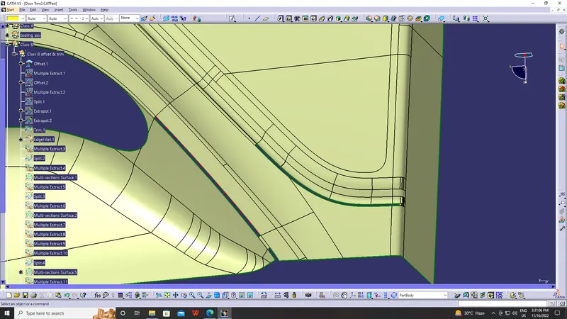
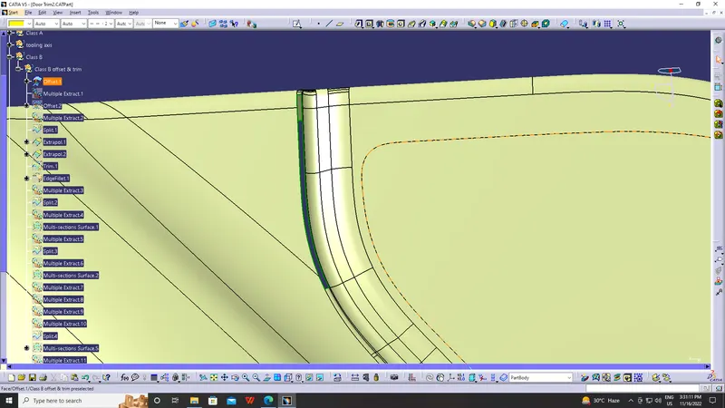
- Rework on the patches and discontinuity of the offset surfaces using the features like extract, multi-extract, sweep, multi-section surfaces, extrapolate.
- To ensure the continuity of the Class-B surfaces check the boundary command to find out the boundary.
- Hence class-B surface creation is done.
SURFACE-C Creation
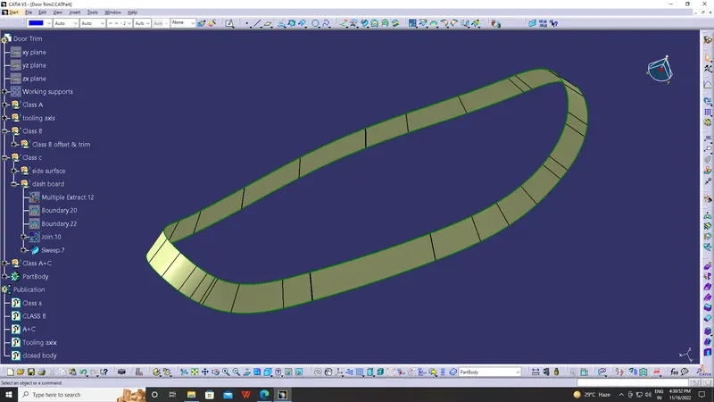
Surface that joins class-A and class-B surfaces is class-C surface. Class C is often specified for interior surfaces not readily visible, surfaces that will be covered by another part when assembled
Since it is a complex class-A surface, we cannot simply create the class-A boundary curve and sweep it at one shot. Hence, we need to create smaller curves using multi-extract command and then create sweep of 90 degree with reference to the surface option. sweeps at the midportion of the bumper should have a 90 degree vaue to pass the draft analysis.
Take Bounday command extrac the boundary
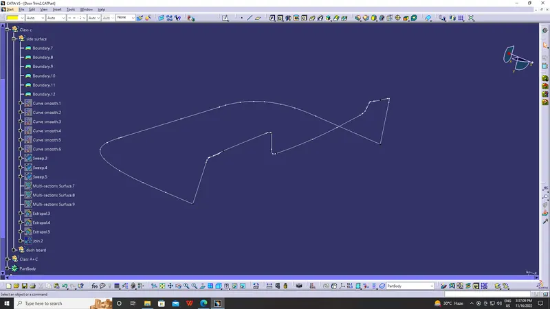
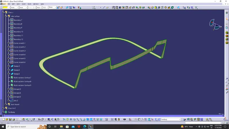
Give some extrapolate to all side it intersect with class B
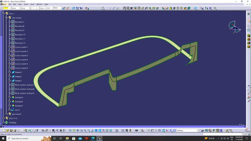
Join Class A with C and Trim This with Class B
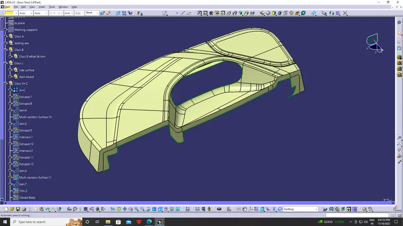
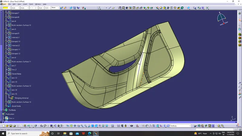
Close Body
In part click on close surface then it will be crate part body
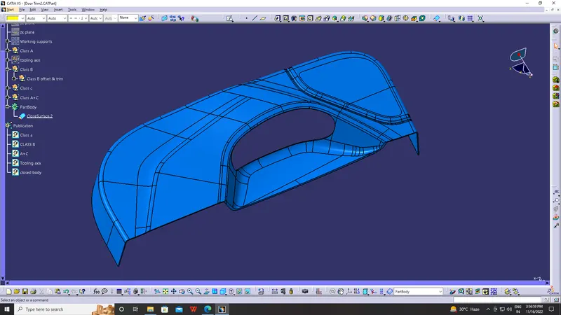
Draft analysis of the Final part body
Same procedure for the draft analysis of CLASS-A surface is followed.
- Change the view mode to material shading
- Align the Compass with Tooling axis.
- Lock the draft direction and perform the Draft analysis.
What are Heat Stakes?
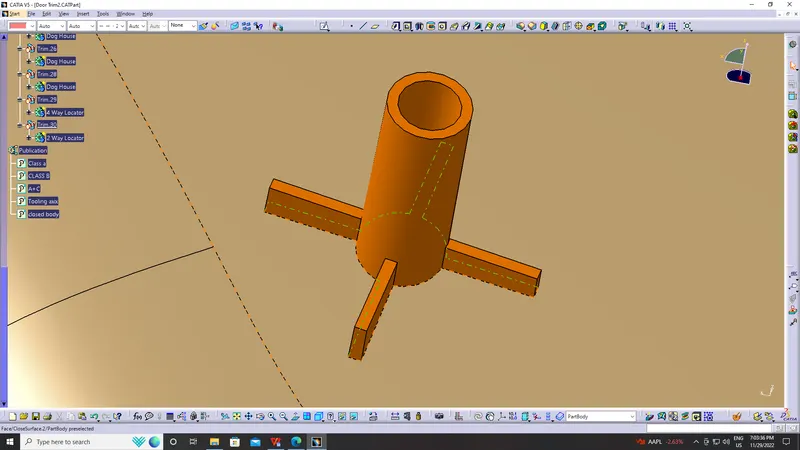
Heat Staking is a joining technology to join two or more parts together where at least one is made out of plastic. The process is used to melt and deform the plastic material using heat and force at a set process time.
Creating of heat satkes:
- At given every point need to create the Heat Stakes
- The outer dia is 7mm & inner dia Of 5mm.
- pad upto 20mm.
- craete rib to give support to the heat satkes
- he lenght of 22mm*22mm.
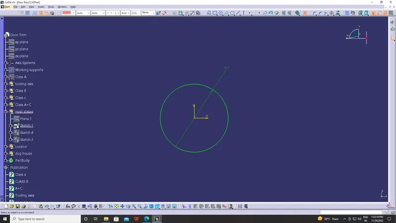
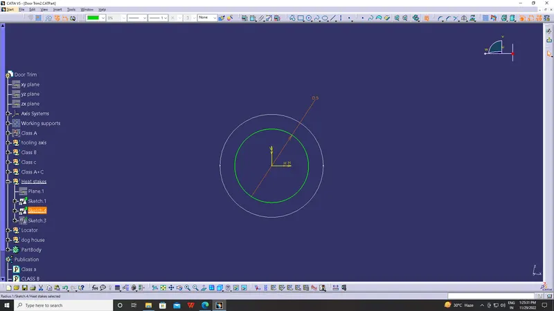
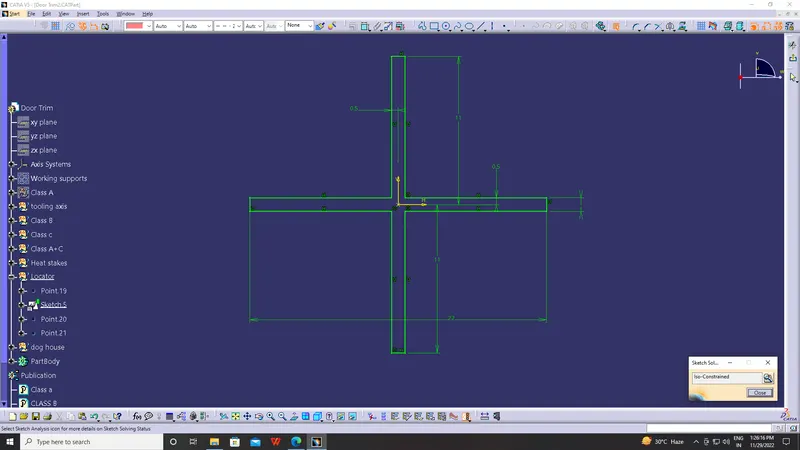
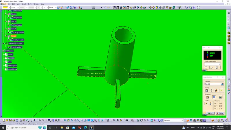
Draft Analysis of heat stakes
Draft Degree is 0.45
What are Locators?
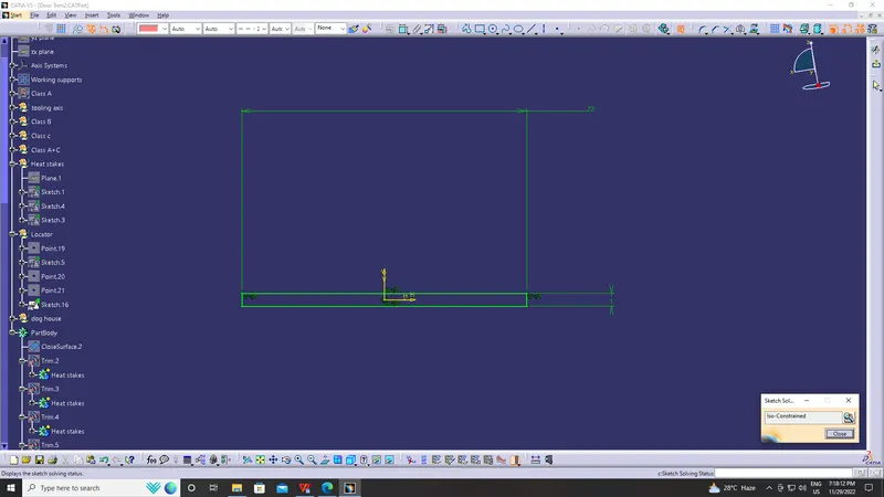
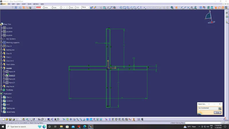
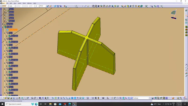
Locators are used to arrest the Degrees of freedom of a component, there are many ways of creating locators based on the model, here for this model, I have created four way n two locators at corner position. The Locators sketch is padded along Tooling axis sirection with thickness to obtain the locators.
Creating Of Locator
- Take Axis System to tooling axis & Creat Sketch.
- the length is 22mm*22mm & pad it for 23mm
- give draft of 0.5
2- way Locator
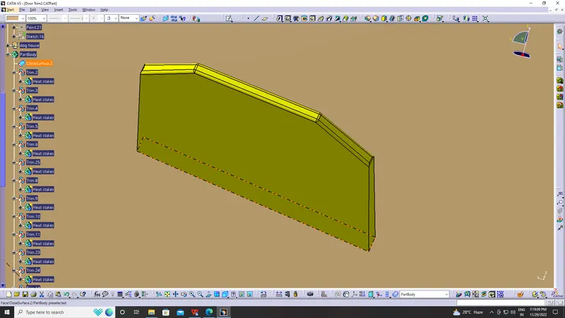
Draft analysis
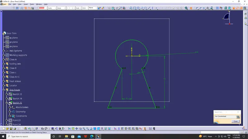
What are Dog House?
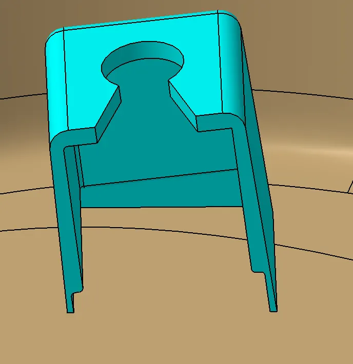
Dog house is an engineering feature used in plastic trim design. Dog houses are used as supporting feature. Sometimes other engineering features like snaps; locators etc. are mounded on them to increase their strength. Dog houses are subjected to draft analysis to prevent breakage of the component during ejection from mould cavity.
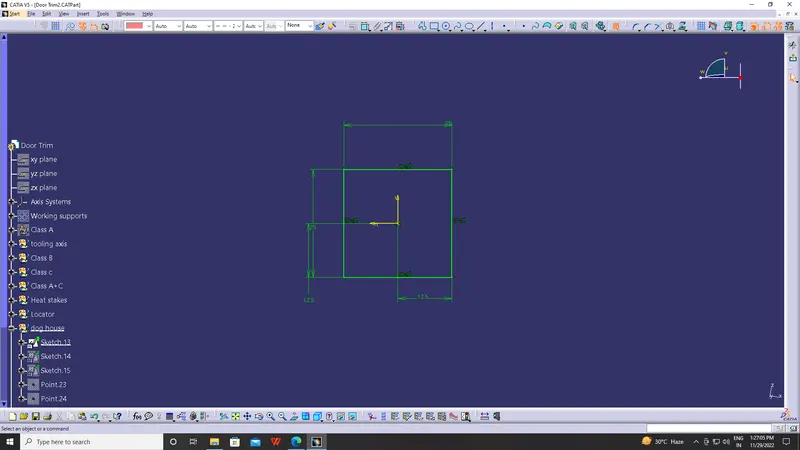
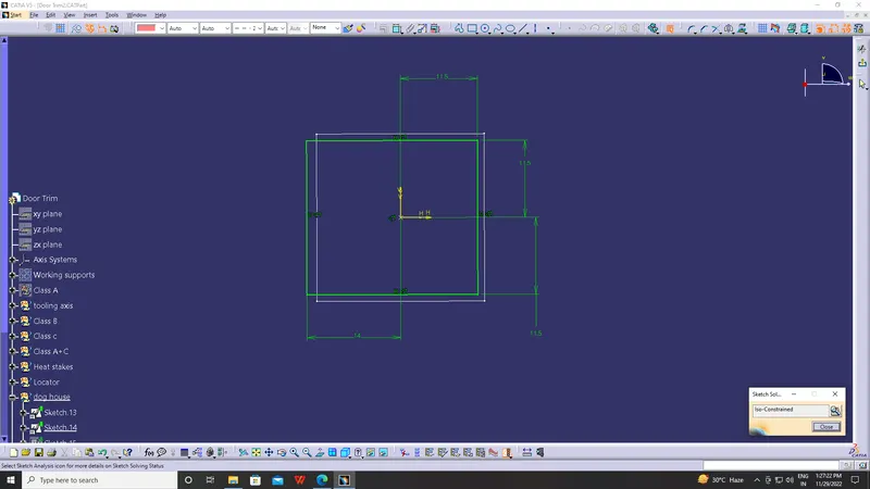
- As per rules of dog i have created 25mm*25mm dog house
- pad it for 28mm & give fillate ouside 2.5mm & inside of 0.5mm.
- give draft of 1.5 ouside and inside 0.5
- using transformation features like rotaion & Transpolation to roatate & Move from point to point.
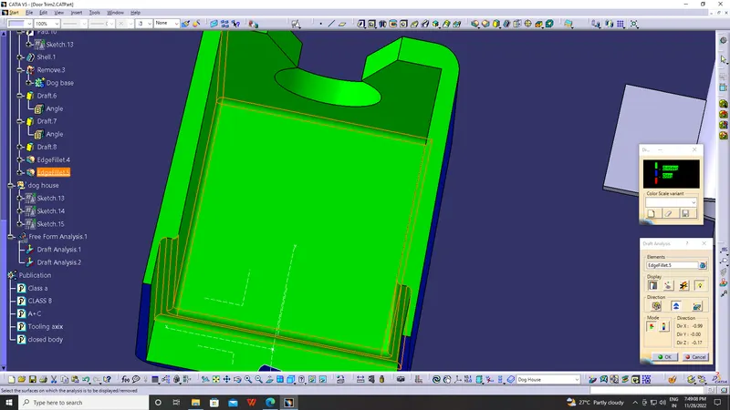
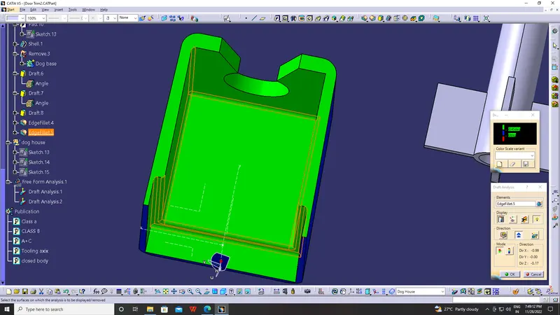
Draft Analysis
- The Dog house Outside is cleared by tooling axis & Inside portion is cleared by side core.
- Draft degree of 0.45
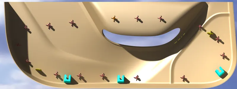
Rendering Of Solid body
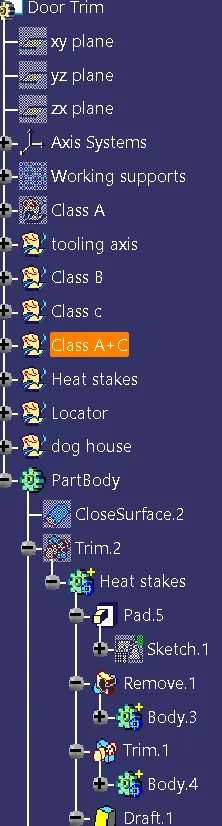
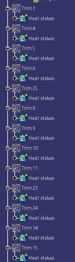
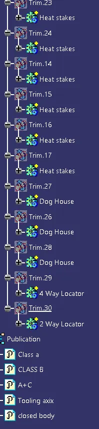
Tree Structure
Conclusion
By the Given class A it is able to convert in solid body & Engineering Features are Craeted on it. And it is ready for maunfacturing.