Week 9 - Project 1 - Door Trim Lower with Engineering Features
Week 9 - Project 1 - Door Trim Lower with Engineering Features
OBJECTIVE
- To determine Tooling Axis for the given Class A surface of Door trim lower
- To design and develop Class B and Class c surfaces from the given class A
- To create Locators and heat stake of the component
- Then develop and design Dog House and Stiffener to the Door trim Lower.
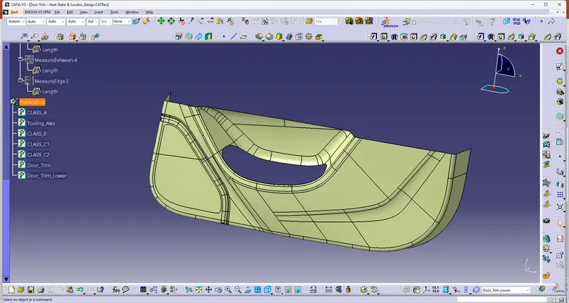
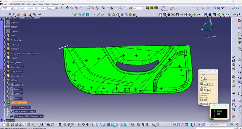
Screenshot of Class A surface
Tooling Axis
- Multi Faces or surfaces in the componenet.So,To Determine possible tooling direction.
- By Y direction Draft analysis is generated to the Door Trim Class A surface.
- Afterthat, Y direction is possible tooling axis is considered.
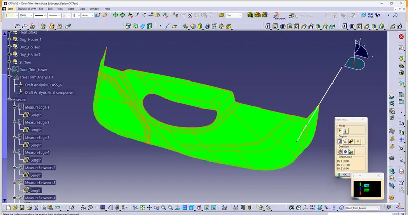
Draft Analysis of Class A surface
CLASS B Creation
- By offsetting the Class A surface at 2.5mm distance (Because component thickness is 3mm).
- Somewhere surface section are break by offset the surface
- where, sections are broke are reconstruct by using Extract, Untrim and Extrapolate features
- then Combine those section to the Offset surface.
- After the Class B surface as Created
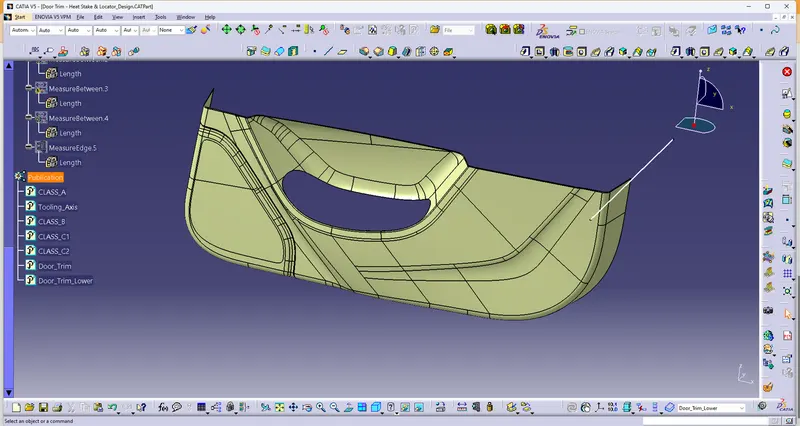
Screenshot is shown as CLASS B surface
CLASS C Creation
- From the Class A surfaces using Boundary command to all edges of the surface
- then sweep those section by define by reference surface with guiding of boundaries
- sweep at the angle of 90 degree at distance of 7mm
- then one sweep to another edges are extrapolate 2mm and trim those edges.
- after that join all Sweep section of the surface and considered as Class C surfaces.
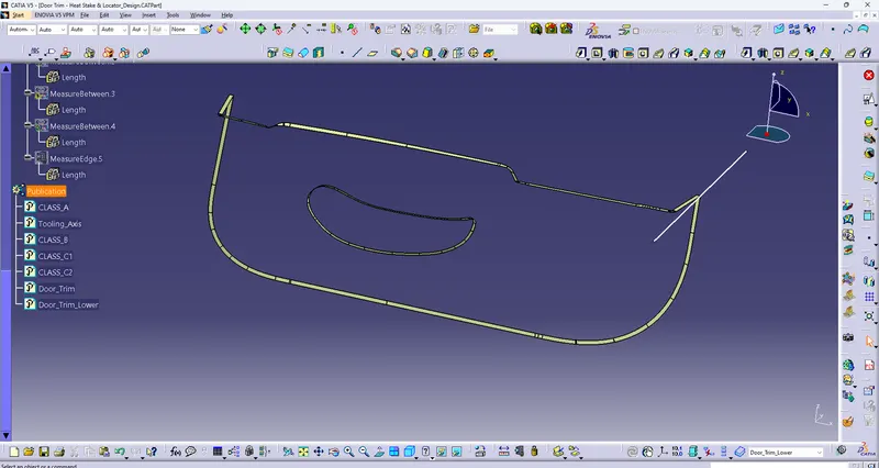
Screenshot of CLASS C surface
FINAL Door Trim Lower Creation
- Join Class A and Class C surfaces
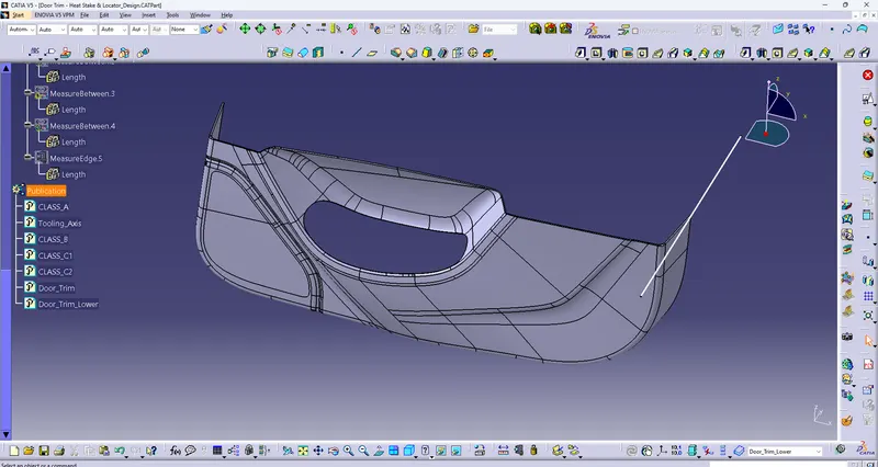
- Then Trim Class B and Join of (Class A and C surfaces).
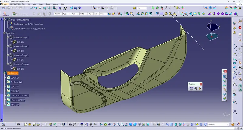
Screen shot of JOIN both Class A and C surfaces
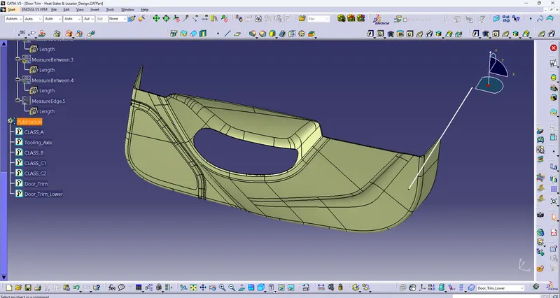
Screenshot of Trim of Class B and Join (Class A and C surfaces)
Locator Creation
- To create point and plane on the surface, then positioned sketch draw two lines with length of 15mm and constraint to coincidice to each other with Iso constraint.
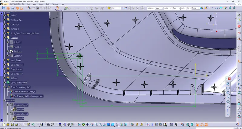
- After that create pad operation with direction of tooling axis at distance of 23mm
- then Draft all the faces to tooling axis at 1.5 degree
- then fillets all corner edges and Chamfer the ends of four sides of ribs
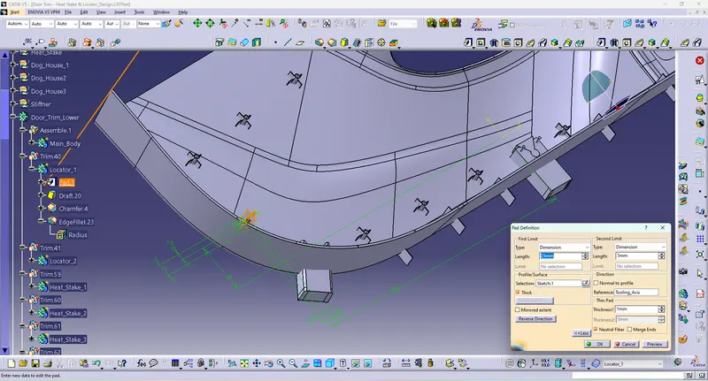
- Then union trim two locators to the main component
Heat Stakes Creation
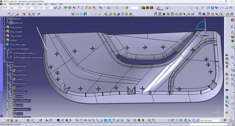
- Positioned sketch,on the surface at given heat stake point as projection point and draw circle of Dia 7mm
- then sweep to Reference with Drafting Direction is Tooling Axis and thicken to 1mm and its create inner hollow dia is 5mm
- Draft angle of 1.5mm to the tooling axis direction and fillet
- then create ribs side support of heat stake at15mm and pad with tooling axis
- then draft angle of 0.5 degree and fillet to 0.25mm
- from one creation heat stake and copy to create multi heatstakes
- then translation all the points given by the input.
Dog House Creation
- To create point on the surface which dog house as be create and add plane on the surface
- Then positioned sketch, draw a lines for three sides and iso constraint
- after that sweep with reference of drafting direction is tooling axis at 1.5 degree
- then thicken to 2mm and draft angle the sides 1.5 degree with tooling direction and union trim to main component
- then on the dog house surface create point and plane
- afterthat positioned sketch, create circle and two lines at point of circle
- then two lines are 70 degree to distance and trim the un required sketch and iso constraint
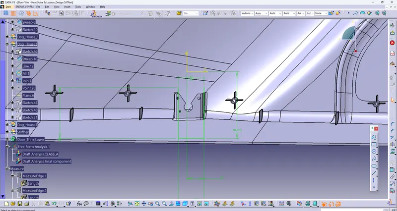
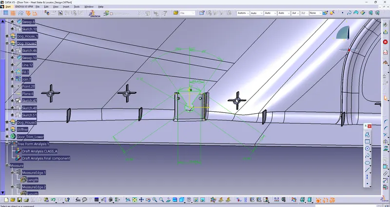
- Pad the sketch and remove on main component
- Create positioned sketch, on same dog house surface and create two circle of dia 3mm
- then pad the sketch and remove to the main component
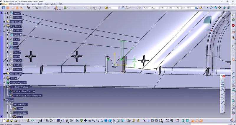
- Then fillet those edges at 1.5mm and same other two dog houses are created.
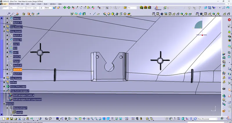
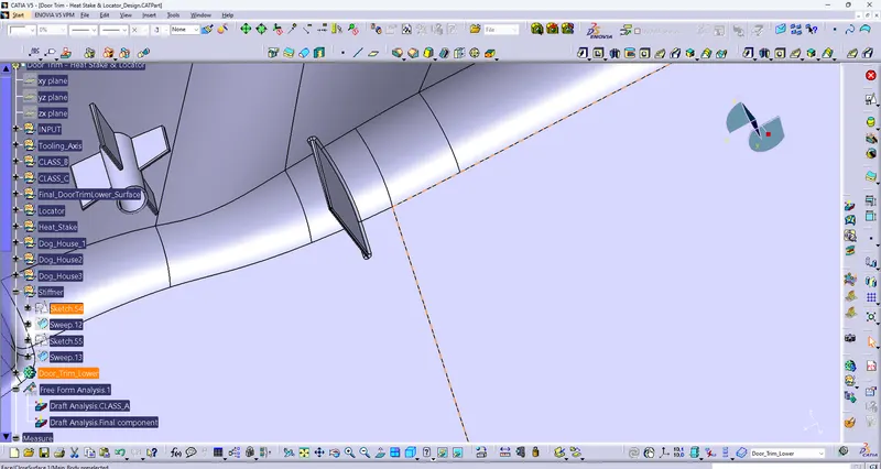
Stiffener Creation
- To create Positioned sketch, on same dog house created plane and create line at 30mm length
- then sweep to tooling direction, 1.5 degree and thicken to 1mm
- then draft angle of 0.5 degree at tooling axis and fillets all edges to 0.25mm
- then create copy of the body and translation to required location
- after that Union trim to the main component and fillet to 0.5mm at the edges
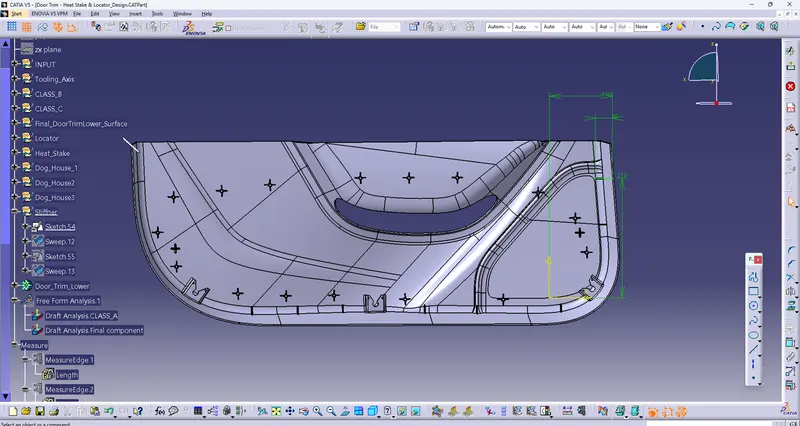
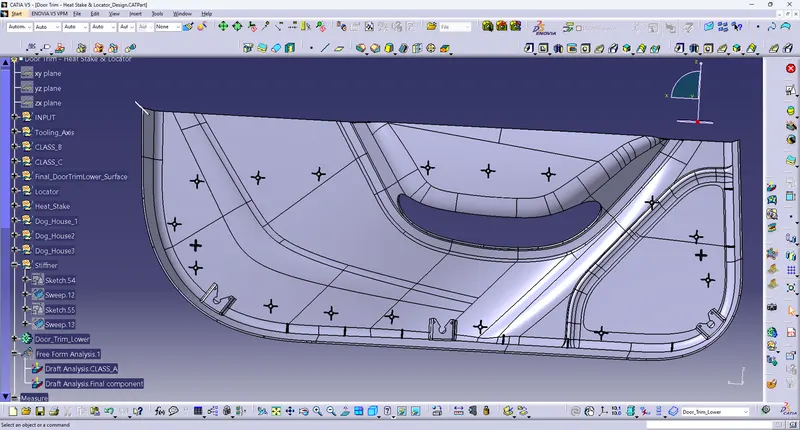
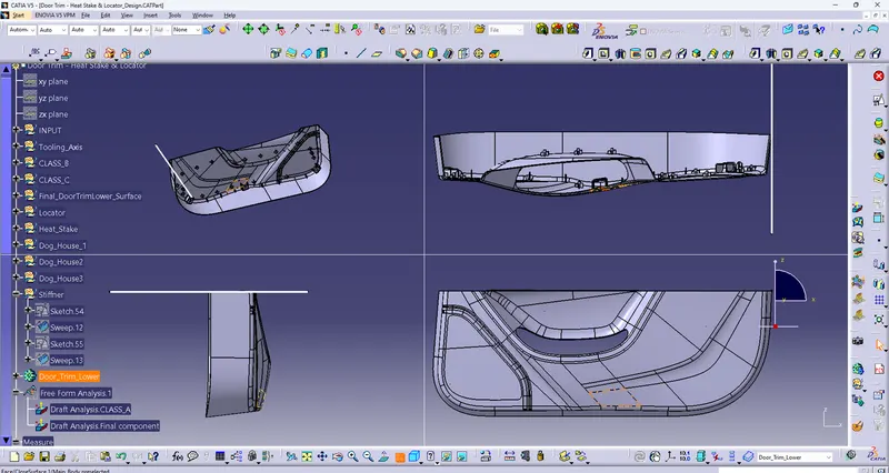
Draft Analysis of final component