Week 9 - Project 1 - Door Trim Lower with Engineering Features
Aim:
To Create the Door Trim Lower Plastic component through the given Class-A surface. To begin with, the tooling axis for the given Class-A Surface should be created meeting the requirements of the draft angle and at the end perform the Draft analysis on the model.
Create the Heat Stakes and the locators considering the design rules mentioned in the video for the door applique.
Tooling axis:
It is defined as the direction in which the mould/core and cavity open. Selection of the direction of the tooling axis depends on the ease at which components can be easily ejected.
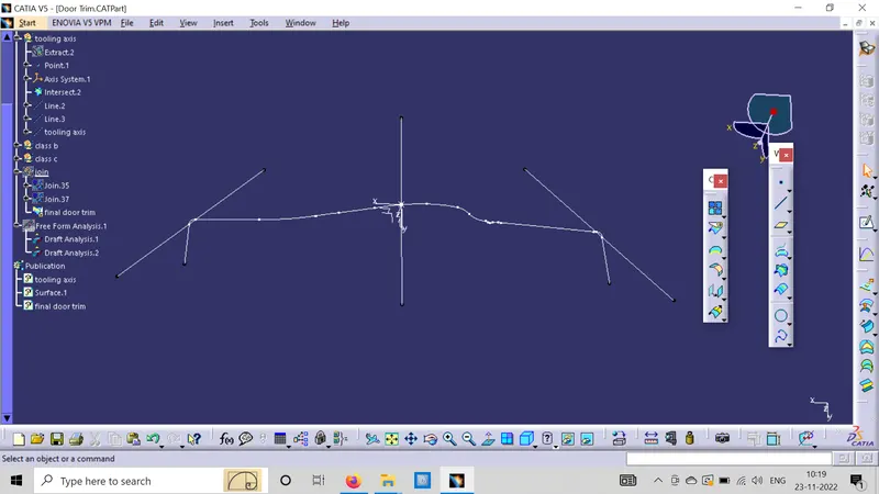
By analysing the component the most easily ejectable direction is somewhere close to the Z direction,(might be inclined to it) so we have made a sketch on the YZ plane of Axis System) to create a bisecting line considering the 2 faces which might be difficult to be tooled.
Draft analysis:
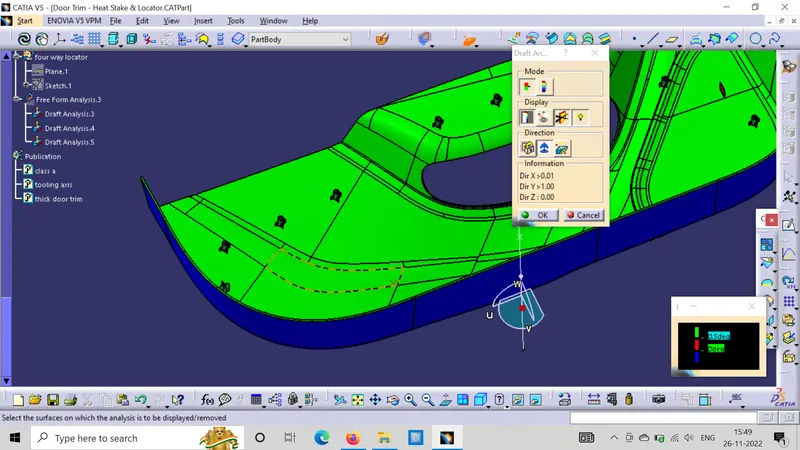
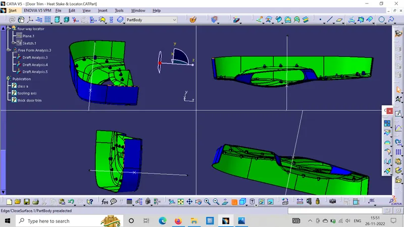
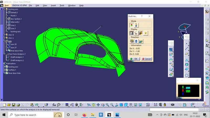
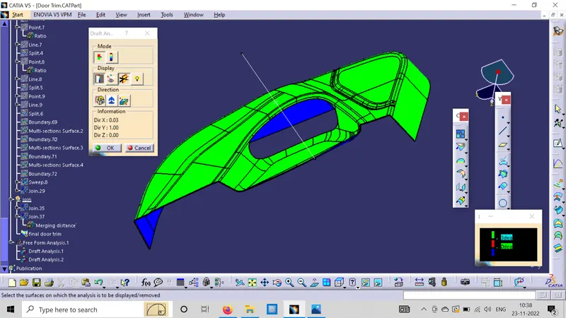
As we know minimum draft angle for the faces of the plastic component should be 3 degrees. So the value of 3 degrees (considering tolerance) is provided in the Draft analysis colour mode window Inside the colour scale, the GREEN bar shows the draft angle of 3 or above 3 degrees. The blue bar shows below 3 degrees draft angle the other limit being and the RED bar shows the negative draft angle. As shown in the image below all the top faces and side faces of the component are green, while the bottom faces are red. The line of demarcation between the green and red faces is the parting line which divides the core and cavity halves. The solid model has cleared the draft analysis successfully as shown in the image below.
Class B:
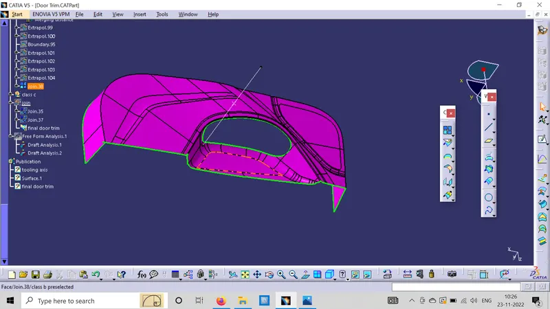
As per the required dimension of thickness 2.5mm then i offset the class a surface and modified the patches failed to offseted.
Class C:
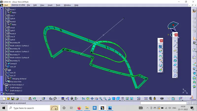
To create the class C surface took the class and using the boundary of it then sweep 3 degree of the surface as intersect the tooling axis and another surface the sweep 90 degree to the reference surface.
Closed surface:
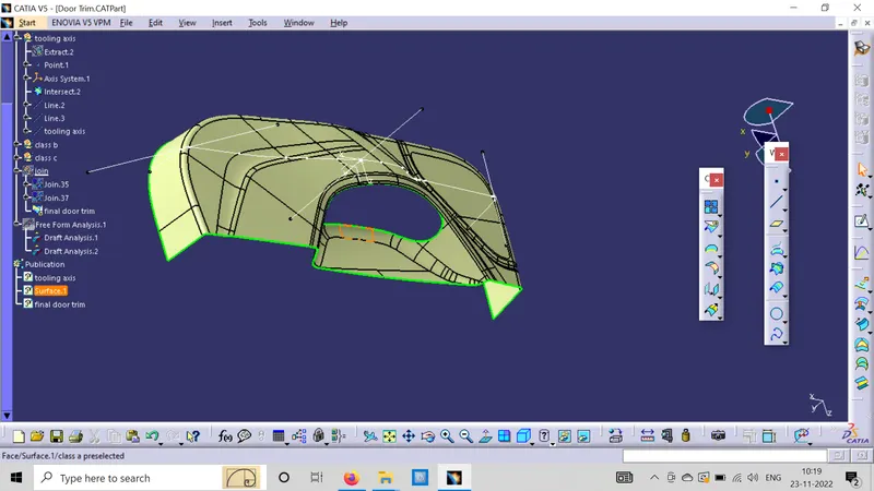
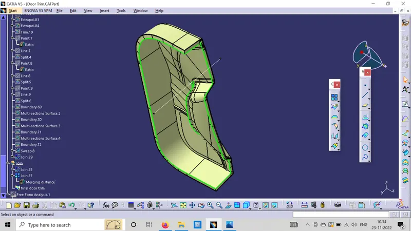
Then join class a and class c and make the final door trim surface through trim join of class a and class using the class b.
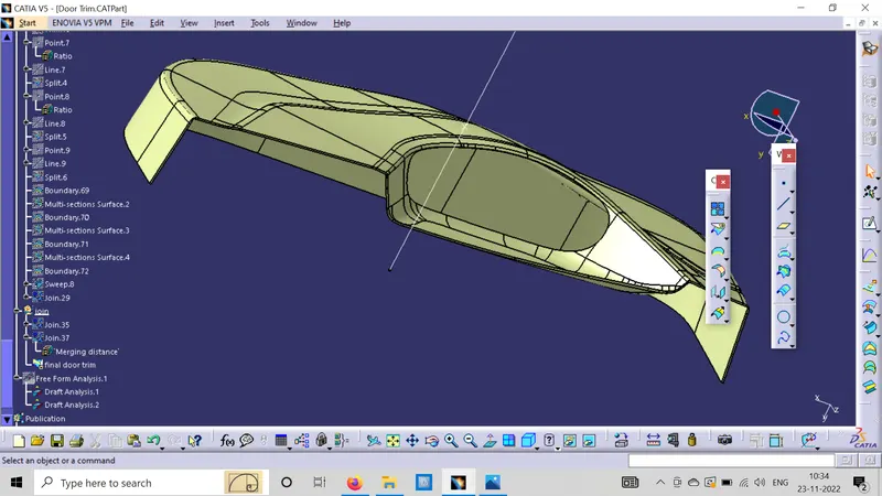
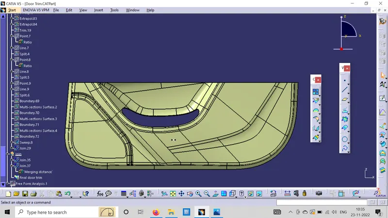
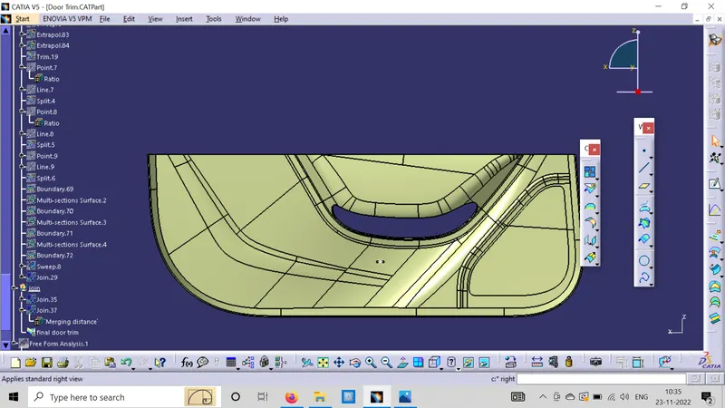
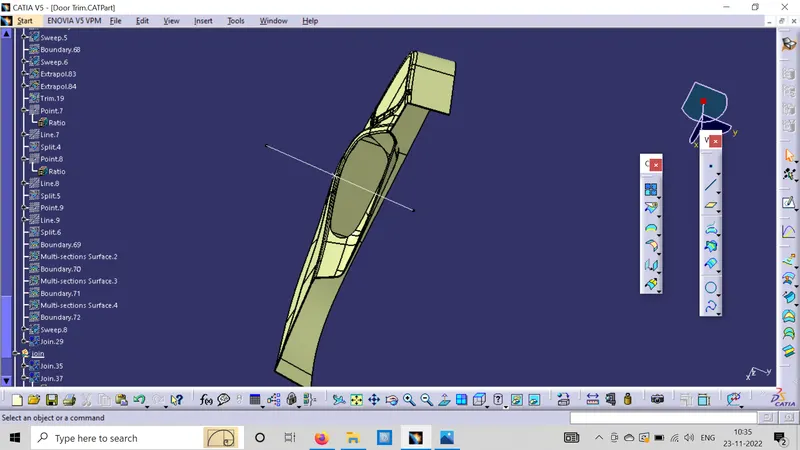
Draft analysis:
Engineering features:
Four way locator:
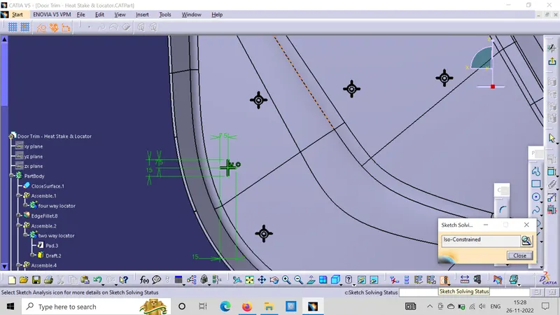
To create the four way locator as an engineering feature in the b side of the part it is used to locate the part in the assembly to negleate the degree of freedom of the part it is based on the 3-2-1 principle.
The four way locator arrest the 5 degree of freedom in linear movement and arrest 6 degree of freedom in rotational movements.
To create the plane on the b side and sketch the line the creates the 4 way path of the length 7.5 mm on each direction then pad it to 20 mm and draft of 0.5 mm then chamfer for entry path 3mmX45 degree and assemble to the part body then finally fillet to 0.3 mm.
Two way locator:
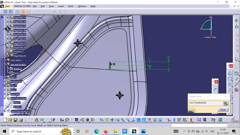
To create the plane on the b side and sketch the line the creates the 2 way path of the length 7.5 mm on each direction then pad it to 20 mm and draft of 0.5 mm then chamfer for entry path 3mmX45 degree and assemble to the part body then finally fillet to 0.3 mm.
Heat stakes:
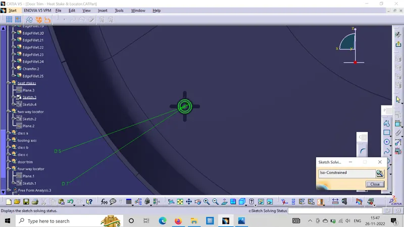
Heat stakes are the one of the engineering features, these heat stakes will enter the mating component and using a heat staking machine these heat stakes are melted and cooled. When cooled this will get hardened and the two components will stick together. Thus all degrees of freedom are arrested.
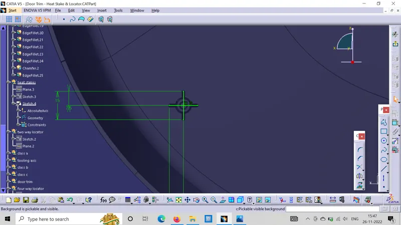
To create the circular with dia inner circle is 5 mm and the outer one is 7mm the pad to 15mm which smaller to the locators and the draft it to 0.5 degrees both sides and fixing heat stakers are sketched and pad it then fillet it to 0.25 mm.
Final draft analysis: