Week 9 - Project 1 - Door Trim Lower with Engineering Features
DOOR TRIM
AIM
Create the Door Trim Lower Plastic component through the given Class-A surface. To begin with, the tooling axis for the given Class-A Surface should be created meeting the requirements of the draft angle and at the end perform the Draft analysis on the model.Create the Heat Stakes and the locators considering the design rules.
PROCEDURE
The main parts we gone construct is TOOLING AXIS, CLASS B, CLASS C, HEAT STAKES AND LOCATORS.
1. TOOLING AXIS
Before we create TOOLING AXIS, we need to check CLASS A surface whethe it have any disconnectivity in between the CLASS A surface. We can check that by selecting boundary tool which in the operation tool bar. After selecting boundary tool we have select the CLASS A surface and if lines are shown ar boundary of CLASS A surface then there no disconnectivity in between. If any lines are shown in between the ClASS A surface we have close that gap by using joining tool.
After checking that, we have to create TOOLING AXIS for DOOR TRIM.Now insert a new geometrical set for TOOLING AXIS. we can create TOOLING AXIS by selecting measure inertia > create geometry > centre of gravity. Then a point will be created at center of the CLASS A surface. After that select line tool and create line from the created poing towards Y AXIS.
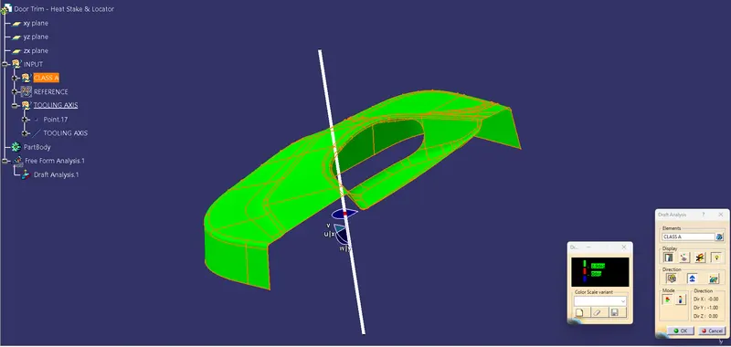
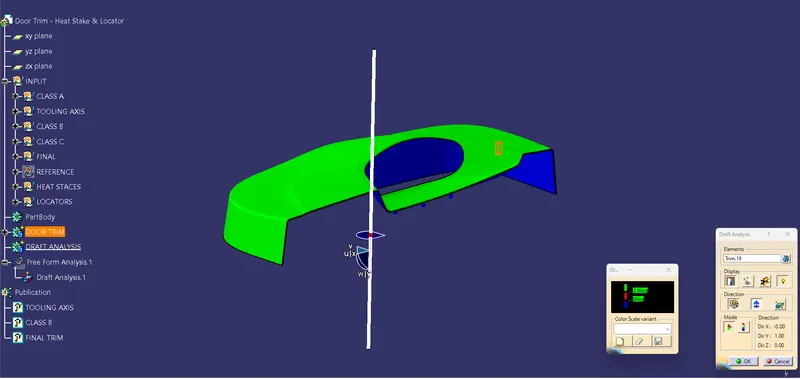
Then go to part design to check the draft analysis for CLASS A.By selecting analysis tool > draft analysis. In that select compass and drag that compass to TOOLING AXIS and lock it. Then select the CLASS A surface, now put the values 2.9 deg for draft angle. Now check the CLASS A surface are green.
2.CLASS B SURFACE
Before constructing CLASS B surface insert a new geometrical set. Select extract tool from operations tool bar and extract CLASS A surface. Now hide CLASS A surface and keep extract part. Then offset the extract part for 2.5mm inside. Now some parts wont be offset but still select ok. Then select boundary tool and click on offset parts and see where are the parts are missing in offse
t.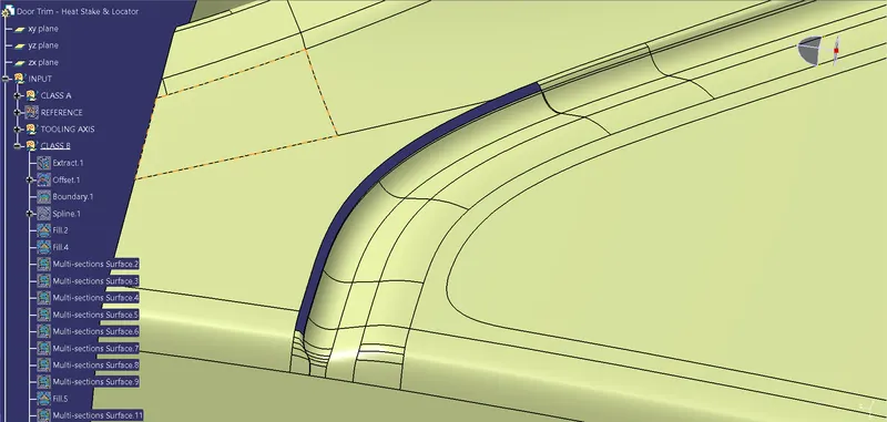
Now fill that gaps with help of multi-section surface tool, fill tool, etc. After filling that gaps once check the offset part with boundary tool whther all the gaps are filled. Now the CLASS B is created.
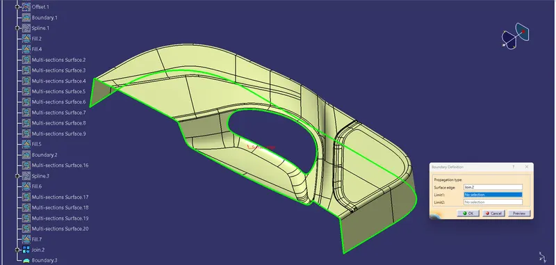
3. CLASS C
Insert a new geometrical set for CLASS C surface. Unhide the CLASS A surfrace, then select boundary tool and click on CLASS A surface. Now the lines are created at edge of CLASS A surface. Then select sweep tool and click on edge lines, then select subtype as with reference surface. Now for guide curve as edge lines and references surface as CLASS A, then give 90 deg angle with 4mm length.
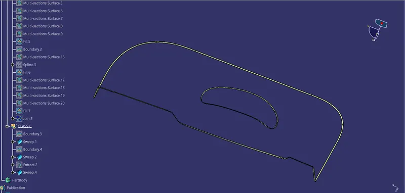
Now check the CLASS C surface with boundary tool whether is there any gaps in between the CLASS C surface.
FINAL TRIM
Insert a new geometrical set for FINAL TRIM. Now join the CLASS C surface with CLASS A surface, then trim that join with CLASS B surface. Then select boundary tool and click on FINAL TRIM to check is there any gap in between the parts, if the error came when selecting the FINAL TRIM then it is fully closed.
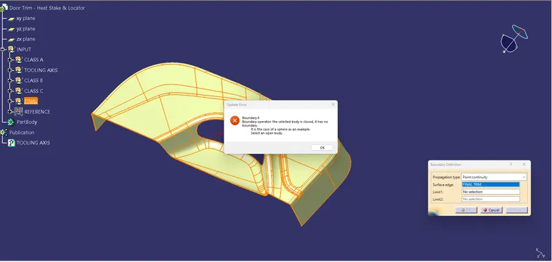
Now go to part design to make the soild part from the FINAL TRIM with the help of close surafce tool which is in surface base features.Now the soild part is constructed.
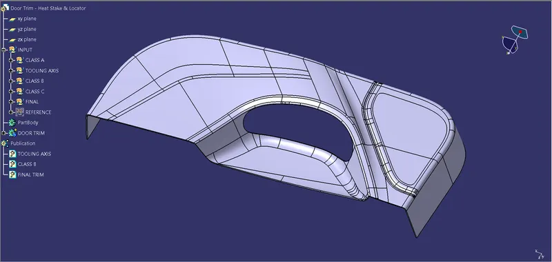
HEAT STAKES
Insert a new geometrical set for HEAT STAKES, then create a 10 or more points on surface of the soild part. Then select sketch to draw the circles on that point, before that create a plan on the point.
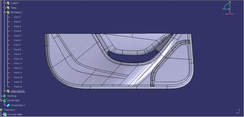
Now the draw a circle on the point with 10mm outter dia and 7mm inner dia. Then check the sketch with iso constructed.
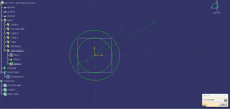
then insert a body, then pad that setch to certain length or up to surface of the soild part. Then give draft angle to HEAT STATKES with the help of draft angle tool which in dress up features tool bar. Give 0.5 draft angle as up per the design rules.
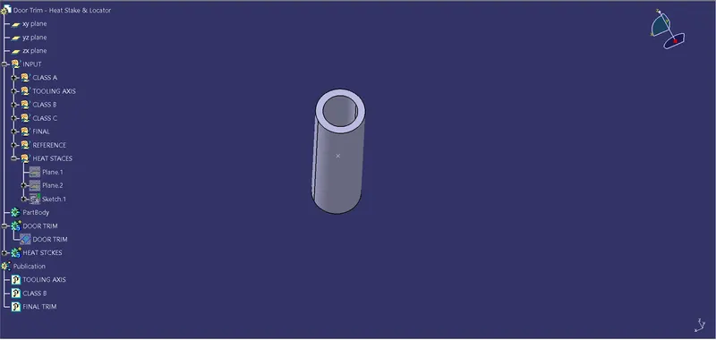
Then give ribs to HEAT STCKES for support.
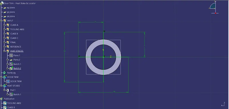
Now do union trim the ribs with HEAT STAKES.
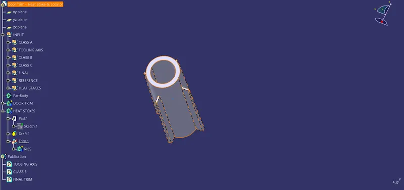
Now the HEAT STAKES is constructed as per the design rules. Now copy this specific body and past with another one to translate the HEAT STAKES with other points. Then the HEAT STAKES is constructed to all the given points.
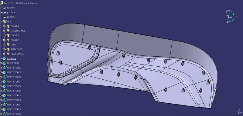
LOCATOR
Insert a new geometrical set for LOCATOR. For LOCATORS there two type one 4 WAY LOCATORS and 2 WAY LOCATORS, for this DOOR TRIM we gone create 4 WAY LOCATORS. Draw a + symbol line on the surface with certain length.
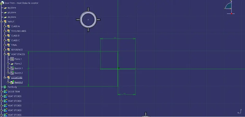
Then pad that sketch with certain length. make sure that the its over the HEAT STAKES, since the LOCATORS are the fisrt to mat with other parts.
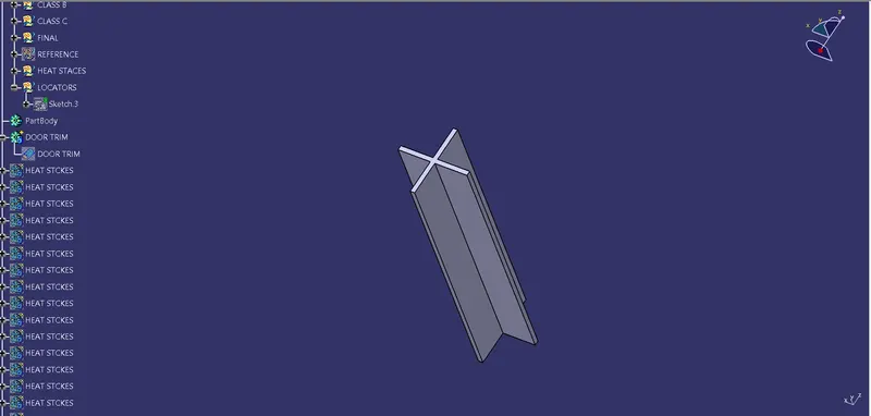
Now do draft angle on LOCATORS with the help of draft angle tool. As per the design rule we should give 0.5 deg draft angle to LOCATORS.
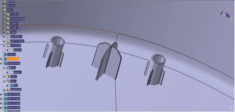
Now do union trim the HEAT STAKES and LOCATORS with main body DOOR TRIM
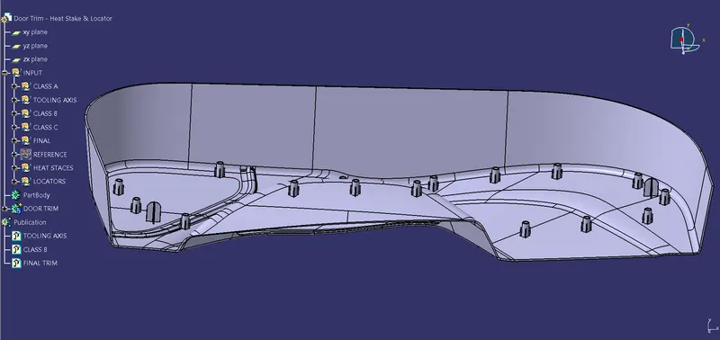
DRAFT ANALYSIS
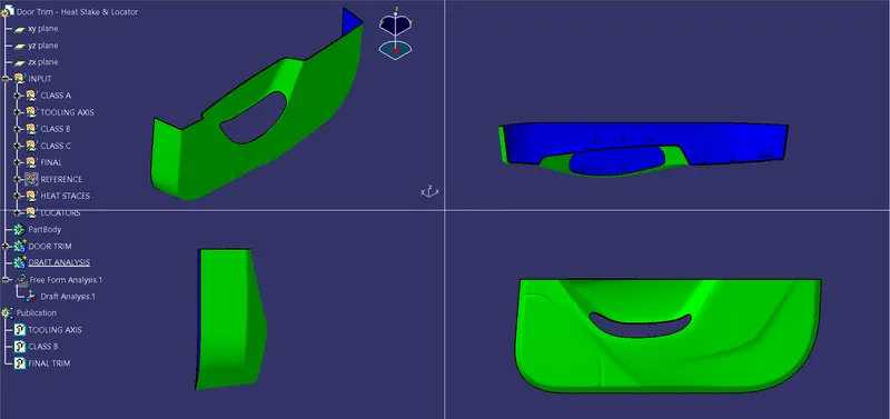
Insert a new body for draft analysis. Now select draft analysis tool which is in analysis tool bar, then select compass and drag that compass to TOOLING AXIS and lock it. Now select the DOOR TRIM body and check the draft angle of it. The draft angle should be 2.9.
RESULT
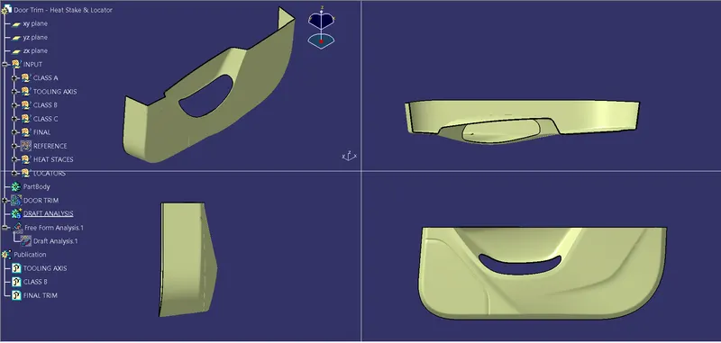
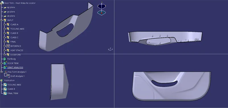
Hence we have constructed the DOOR TRIM as per the design rules