Week 9 - Project 1 - Door Trim Lower with Engineering Features
Aim: Create the Heat Stakes & locators for the Door Trim lower considering the design rules and perform the draft analysis for class A and create the final close body component and perform the draft analysis.
Objective:
a) Create the Tooling axis
b) Design the class-B and class-C surfaces and join them.
c) Use the Close Surface feature to make a solid body from the surface.
d) Design the required dog house and analysis them.
e) Perform the Draft analysis for the final component.
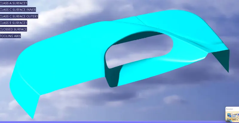
- Using Given Class A Surface Input.
____________________________________________________________________________________________________
CREATION: Final Component using input.
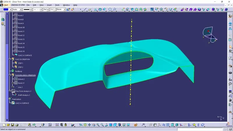
1. Tooling Axis Creation: Class-A surface is first analyzed to create the tooling axis. where the molds pull apart in injection molding. Tooling direction is essential for plastic product design as it decides the direction for mold separation.
To create the tooling axis first we have to check the best suitable direction for tooling by using the compass. the y direction is suitable for creating the tooling axis because in the y direction most of the surfaces are clearing while performing draft analysis. Generally tooling axis is created using bisecting line method but here A line normal to the surface is created in the y direction and considered the tooling axis.
2. Draft analysis of Class- A -
After creating a tooling axis we do the draft analysis. Before drafting we have to make sure that in the view mode it is selected for the materials.
After selecting the feature draft analysis tool we drag the compass from its position to the tool axis. Then lock the compass. After that select anywhere on the component and
it will give you the result.
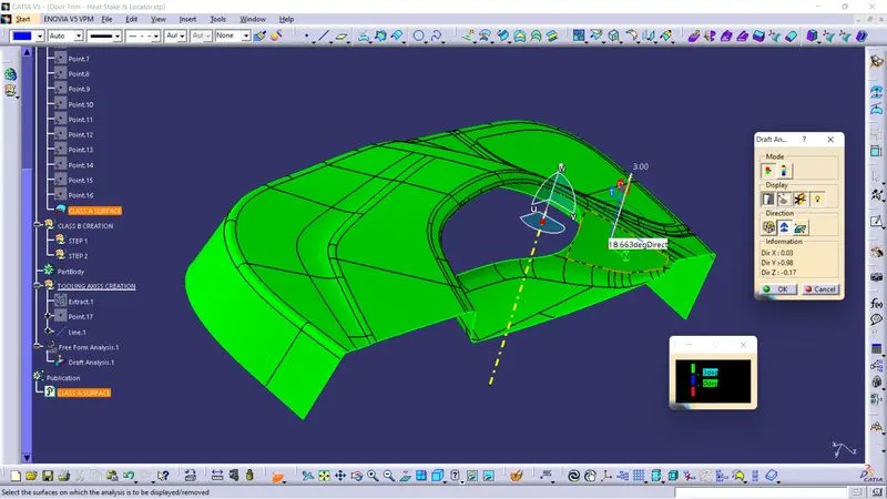
We change the minimum draft for the component to 3°.
We can use the running point option to check the angle of the component. - Y direction.
3 Class B surface creation:
In this component Creation of the class B surface first, we have to offset the entire model by 2.5mm outward some of the surfaces give offset error and ask for an offset without these subelements click okay and work on the incomplete surfaces by using the multi-section surface command, sweeps and different commands used to complete the class B surface.
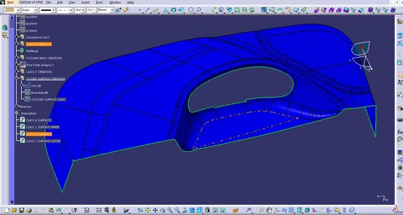
Incomplete surface gaps in the offset. so we work on the surfaces and ensure that there is no gap in the class B surfaces.
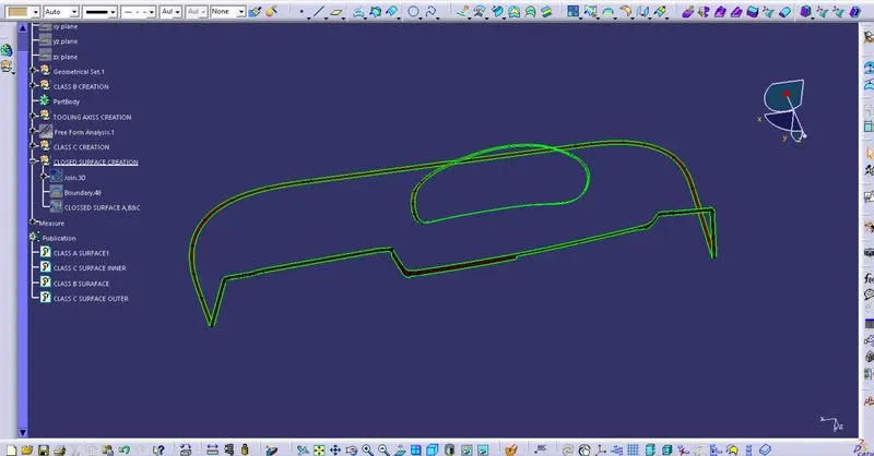
4. Class C surface creation :
We first extract the edges from the Class A surface with the help of the multi-extract or boundary command which we create the path for a sweep for class C
5. Closed Surface creation:
like this, we have to create all separate sweeps and join them together. once all the sweeps are joined together we created a class c surface.
Joining class A surface and class c surface together
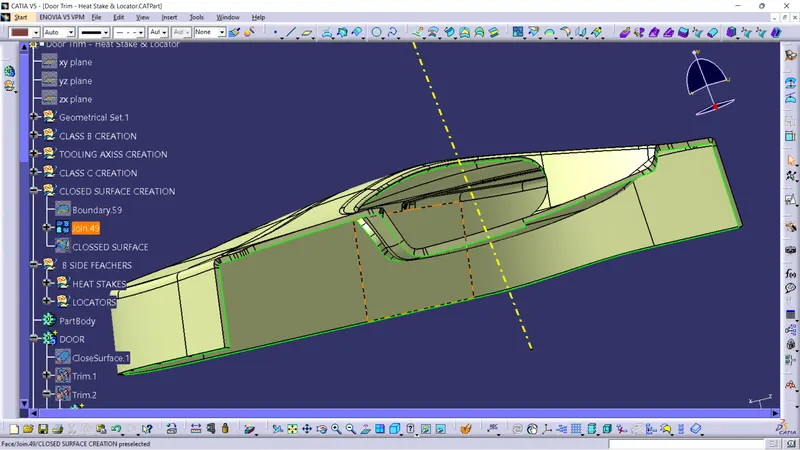
Then trim the class-B surface to join (A+C) this will make sure that we get a closed
surface. We can check it using the boundary tool, if it gives an error that means that the
component is closed.
Now apply the fillet value to the side wall and outer edges.
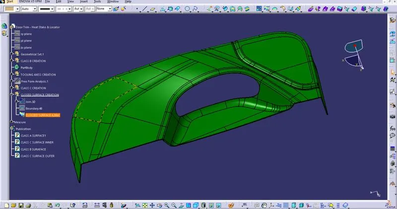
Then We go to the part design workbench and use to closed surface tool to create a
solid body.
hence, we created our final Solid component.
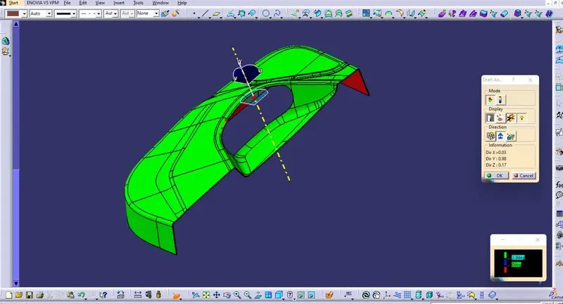
6 Solid Body & Draft Analysis :
1. The part created has to be changed to the material mode in the display frame.
2. Compass is enabled and aligns it along with the tooling direction.
3. The lock command is then applied to fix the compass along with the tooling axis.
4. Color codes are classified and Draft angle is applied.
5. Running point analysis is used to display permissible draft angles.
B - side features creations:
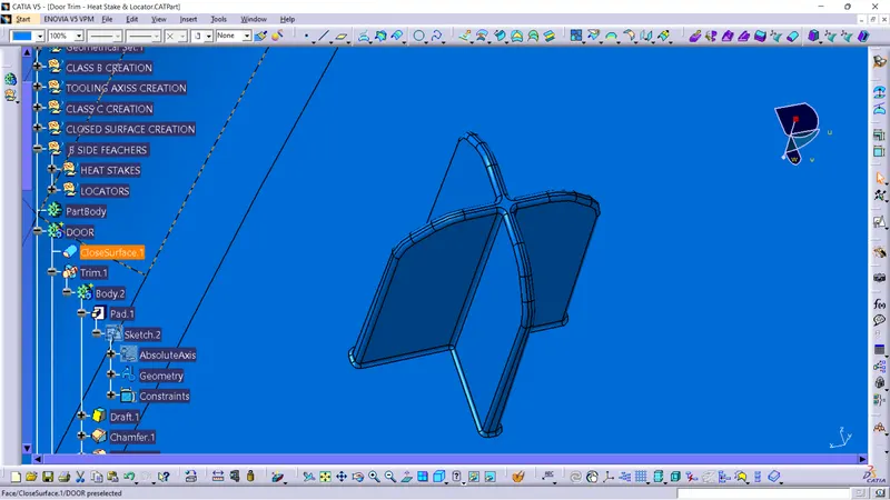
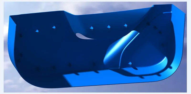
1) 4-Way Locator:
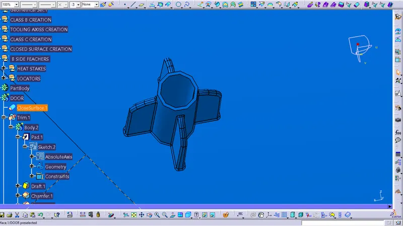
2) Heat Stakes :
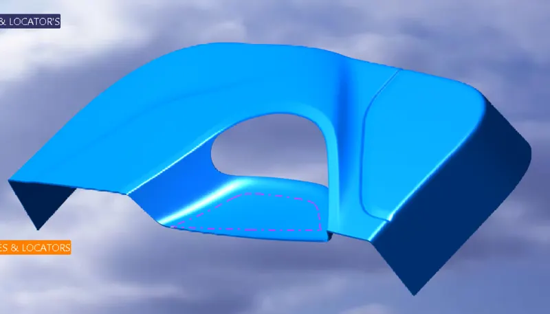
Final Body attached B-side Features :
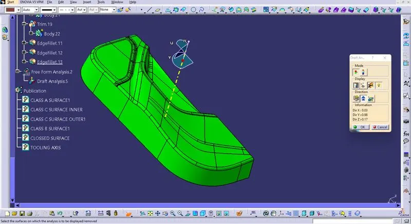
Draft analysis of the final component considering the main tooling axis as the tooling direction
Draft Analysis on the final component:
1. The part created has to be changed to the material mode in the display frame.
2. Compass is enabled and aligns it along with the tooling direction.
3. The lock command is then applied to fix the compass along with the tooling axis.
4. Color codes are classified and Draft angle is applied.
5. Running point analysis is used to display permissible draft angles.
Draft analysis on the 4 way locators and heat stakes considering the axis as our tooling direction
Draft analysis of final component considering the main tooling axis as the tooling
direction
Conclusion :
Hence, B - side features (4-way locators & heat stakes) for the door trim lower were created by considering the design rules, and the Draft analysis performed on the final component is successfully done.
Thanks & Regards,
Arunendra Vishwakarma