Week 9 - Project 1 - Door Trim Lower with Engineering Features
Aim
Create the Door Trim Lower Plastic component through the given Class-A surface. To begin with, the tooling axis for the given Class-A Surface should be created meeting the requirements of the draft angle and at the end perform the Draft analysis on the model.
Create the Heat Stakes and the locators considering the design rules mentioned in the video for the door applique.
Thickness of the component to be 2.5 mm
INTRODUCTION:
CLASS-A SURFACE: A surface made by the designer which is given as an input to the plastic modeler/ sheet metal designer to work on. It is aesthetic surface and the outer most surface.
CLASS-B SURFACE: A surface below a certain thickness from the class-A surface is class-B surface. This is the surface that contains engineering aspects of a model for example Ribs cutout.
CLASS-C SURFACE: A surface that joins class-A and class-B surfaces together is called as a class-C surface.
Report
A detailed report should be done explaining the draft analysis and the tooling axis creation.
An explanation should be given on the way of creating the tooling axis, particularly the Bisecting method.
Draft Analysis:- Draft is a taper applied to the faces of the part that prevent them from being parallel to the motion of the mold opening. This keeps the part from being damaged due to the scraping as the part is ejected out of the mold, to do that the analysis is done and known as Draft Analysis
Tooling axis: The direction in which the mold or core and cavity opens is called as the tooling axis.
Tooling axis creation
As we can see in 3D the tooling direction should be Y direction we can conclude by seeing that the tooling axis should be in this direction but for surity we need to do a visual inspection from every direction
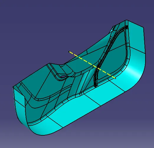
Visual inspection
As we are seeing the class A surface in X direction but not able to see all the faces
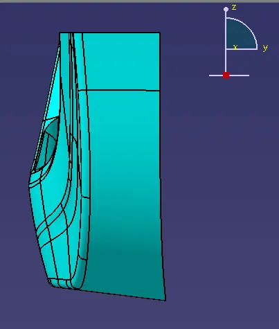
As seeing the class A from z direction but not able to see all the faces
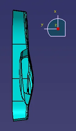
But seeing it from y direction we are able to see all faces thats means the tooling axis will be in y direction
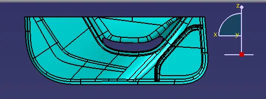
Bisecting Method
The one section surface of the class A was extracted and a point at the centre is created and an axis system was inserted to the point with the current feature is disabled.
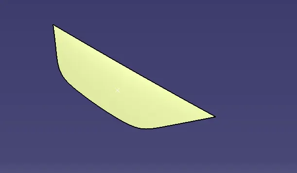
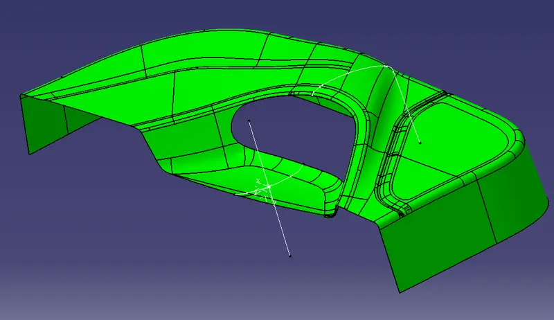
Then bisecting lines with the two inclined lines were drawn
Class A Surface Draft Analysis
The bisecting method is always preferred as the last option so the first method for tooling axis will be create a point on the Class A surface and draw a line in Y direction and this will be the tooling axis
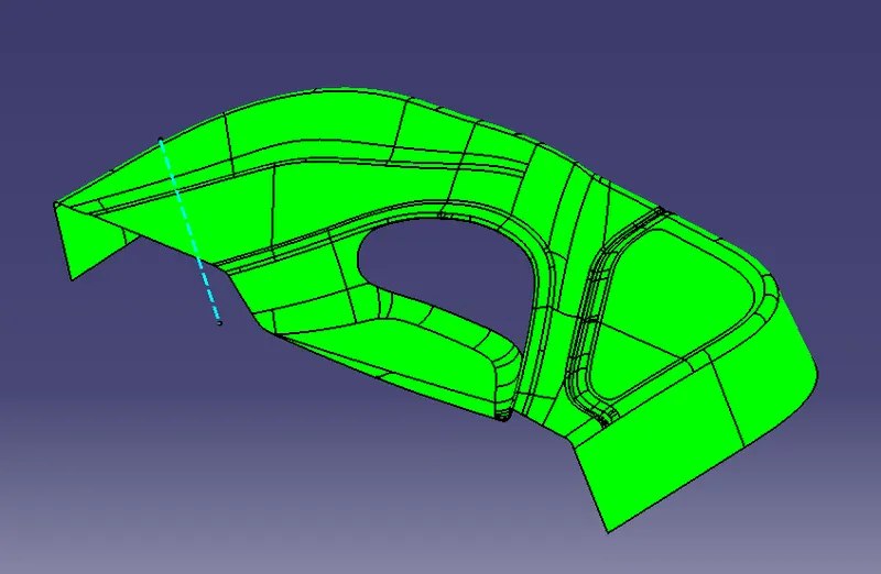
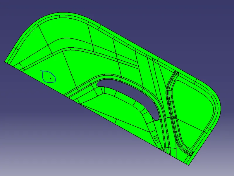
In order to check the correctness off the tooling axis choose tooling axis and select normal to view you didnt able to see the tooling axis by this check we can be sure that the tooling axis is correct
Creation of Class B:
- Now for Class B creation, we need to offset the class A surface inside by 3 mm and this is going to be our B surface
- Then we use the boundary command to check whether this is a gap or missing surface (mostly fillet created this problem)
- Then we need to make the missing surface either use the blend command, multi section solid or the last option is extract the both surface extrapolate it and then trim them and then join them
- At some places there will be gap so you have to extract these 2 surfaces and extrapolate these surface and trim them
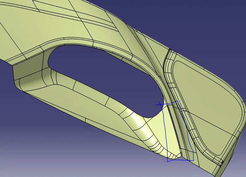
Then use join command to remove the surfaces from the existing body by using sub element to remove which will break the link and not throw error later joining the trimmed surface and this surface
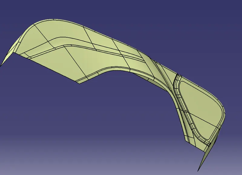
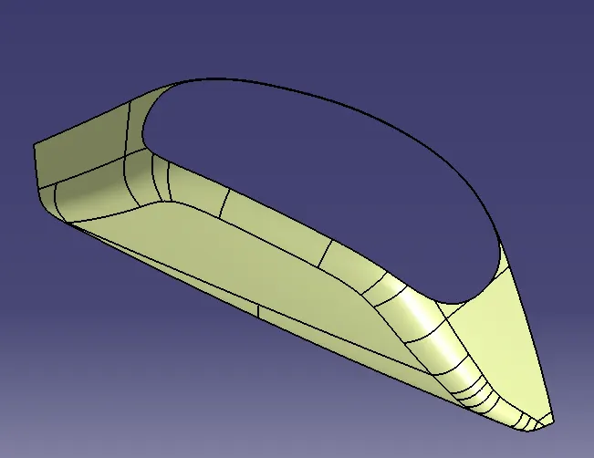
After patching and fixing the gap the outer edges are extracted and extrapolated with curvature continuity.
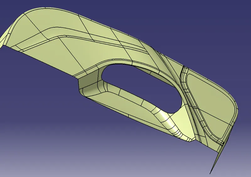
Creation of Class C:
The outer edges are extracted and then using the sweep (with reference surface) command the class C surface is created and at some egdes use the multisection to creat the surface which is not sweep and then join all the surfaces with the Class A surface
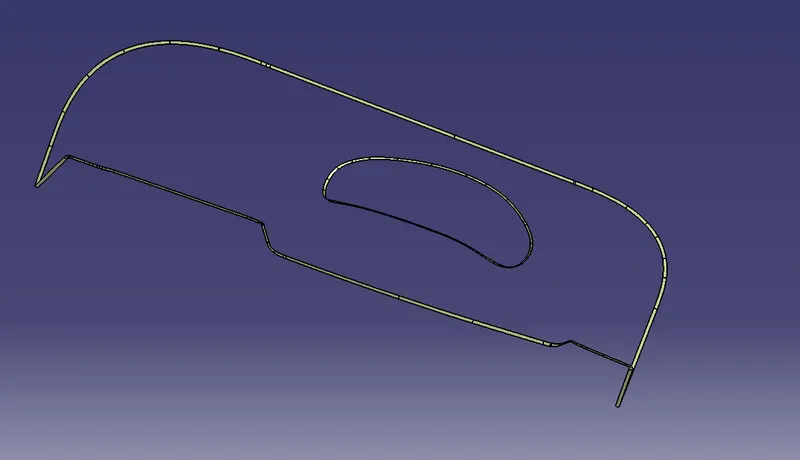
Final Trims:
Class A + Class C:
Then both class A and class C surface are joined to get the surface which is going to be trimmed off with class B surface in order to get the closed surface
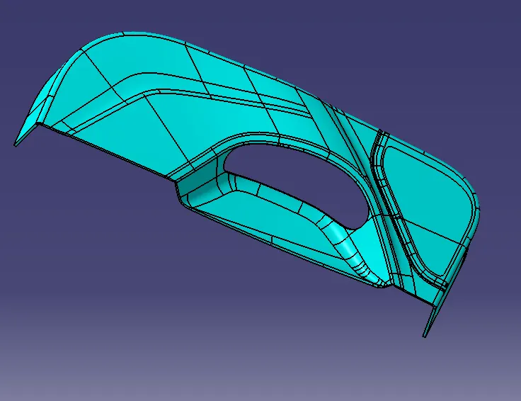
Class A + Class B + Class C:
After trimming we get the closed surface and then we go to part design and use closed surace to create the plastic part
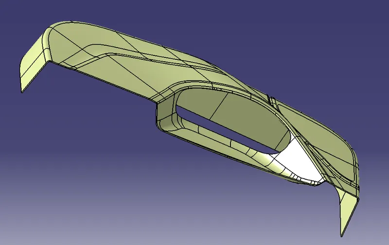
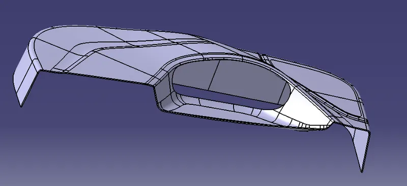
Draft Analysis for Solid Plastic Part
First the class – A surface is checked before creating the Class –B&C surface and finally the solid body must be analysed. Both can be done by following the below procedures.
By changing the view mode to custom view parameters – Material mode then the feature draft analysis is enabled.
Then the compass was activated and placed with the tooling axis by dragging the red pointer and then locked it.
Then, by selecting the quick analysis mode, the nominal value will be 3 degrees and checked for the component's draft angle.
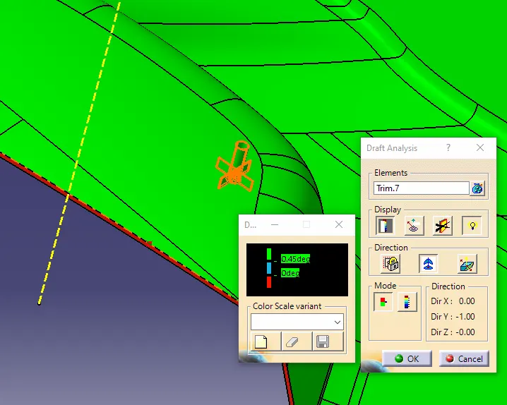
The green colour area shows that it satisfies the 3-degree draft angle. If not satisfied then by using the Running point tool the area is measured and then altered to get a successful draft for the created tooling direction.
And due to Class A surface irregularity there will be some area not clearing draft so we need to communicate and coordinate with Class A design and present them the issue and resolve the irregularities.
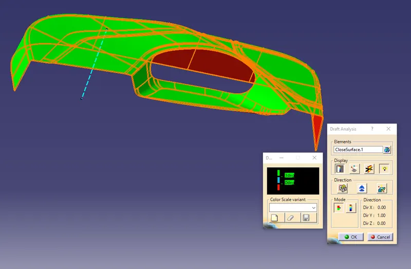
Draft Analysis of Class A Surface
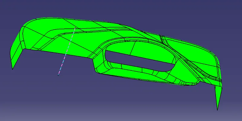
Design of locators and heatstakes:
LOCATORS:
The component used to establish and maintain the position of the workpiece in work holders such as jig and fixture to ensure repeatability of work holder. The locating device for a work holding device mainly depends on the property of workpiece and the overall machining process.
4-WAY LOCATORS:
A round locating pin located concentrically in a hole is a common application of a 4-way pin, and helps to further secure the piece. 4-WAY LOCATORS: 4-way mean you prevent movement at 2 axes (+X, -X, +Y and -Y) on the plane. Generally, you have cylindrical pin on the fixture and circular hole at workpiece part.
Design Consideration
- Height of the locators should be 5 mm greater than the heat stakes because the part is aligned first (Comes first in contact with other part to align) then it is joined by the heat stakes
- Thickness 1.3mm, fillet-1mm and draft angle-0.5degree
- Ideal Chamfer value - 3 mm x 45 degrees
- Ideal length of the locators - 20 mm
- All Locators should be at an equal distance from the surface
- 0.5 mm clearance should be maintained for heat stakes and 0.1mm clearance for 4 way and 2 way locators
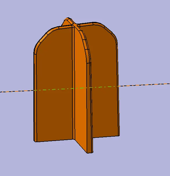
Draft Analysis of 4 way locator
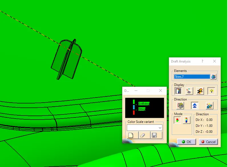
Heat Stakes design
Heat Staking is a pulsed-heat process to join two or more parts out of which one at least is made of plastic. The process is to deform the plastic material using heat and force at a set process time. The bond is made by partially de-forming the plastic part in order to fix the other.
Design Consideration
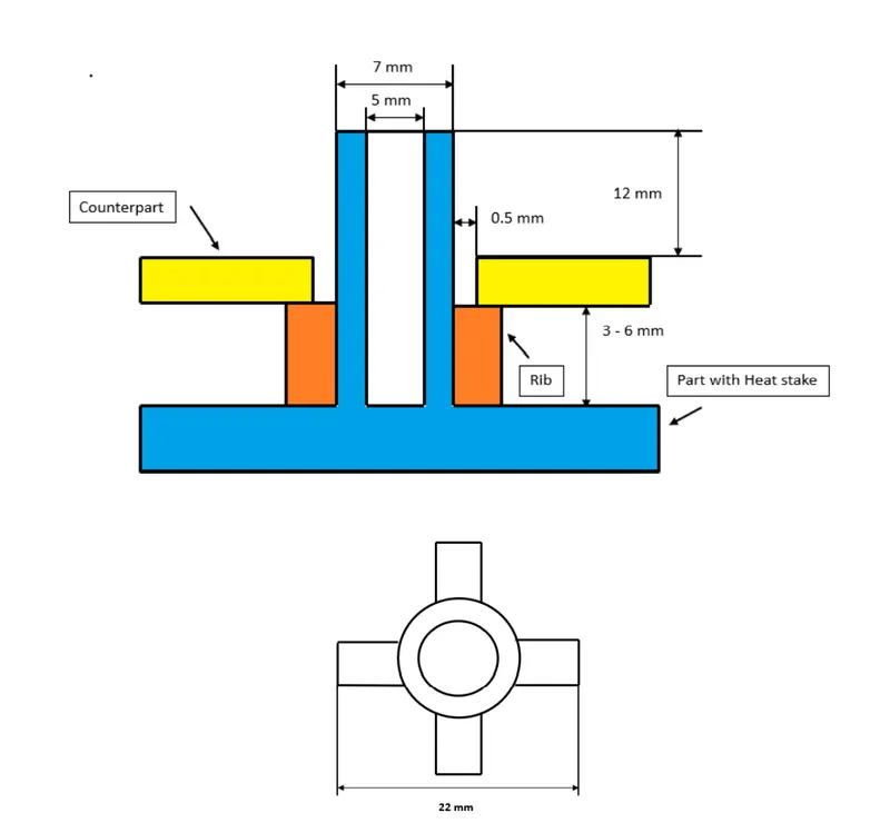
figure 1. heat stakes design
- Counter Part Thickness - Will be given as input
- Component Wall Thickness - Will be given as input
- Length of the Rib - 22 mm
- Height of the Ribs - 3 mm to 6 mm
- Inner Diameter of Heat Stake (d) - 5 mm
- Outer Diameter of Heat Stake (d) - 7 mm
- Minimum clearance between heat stake and counterpart - 0.5 mm
- Height of the Heat stake - Depends on the rib height and counter-part thickness
- Minimum fillet of Heat Stakes - 0.25 mm
- Minimum Draft Angle of Heat Stakes - 0.5 degrees on both inside and outside faces
- Minimum 50mm Gap should be maintained between 2 heat stakes
- 0.5 mm clearance should be maintained for heat stakes and 0.1mm clearance for 4 way and 2 way locators
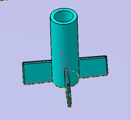
Draft Analysis of Heat Stakes
Submission Requirement
- Screenshots of the completed design in various orientations (Isometric, Front, Side, and Top View)
Isometric View
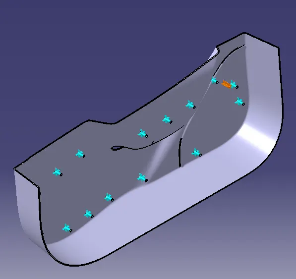
Front Side
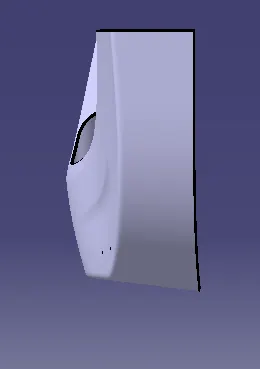
Side View
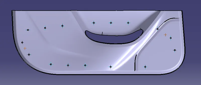
Top View
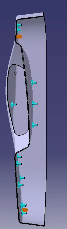
Tree Structure
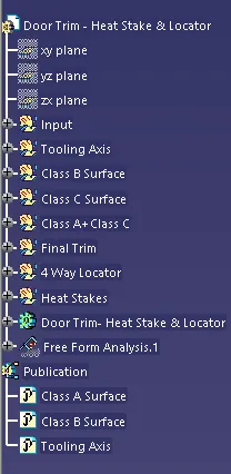
Please find the attached part file for your review