Door Trim Lower with Engineering Features
CREATING TOOLING AXIS
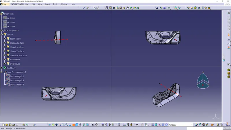
- The axis in which the moment of core and cavity are take place is known as the tooling axis.
- There are three method to create the tooling axis.
- Any one of the standard axis as Tooling axis.
- Creating line Normal to the any one of the surface in the model as tooling axis.
- Creating bisecting line on model and make as tooling axis.
- In this model we use the second method to creating tooling axis.
Creating line normal to the any one of the surface.
- Extact the flat surface of the model to create the point and line.
- Create the point on the extract surface which we want to make a normal line to the surface.
- Then create the line with using the normal to the surface
DRAFT ANALYSIS FOR A CLASS A SURFACE
- In engineering, draft is the amount of taper for molded or cast parts perpendicular to the parting line. It can be measured in degrees or mm/mm (in/in)
- Drafts (or taper) in a mold, facilitate part removal from the mold. The amount of draft angle depends on the depth of the part in the mold, and its required end-use function.
- The draft is in the offset angle in a direction parallel to the mold opening and closing.
- It is best to allow for as much draft as possible for easy release from the mold. The minimum taper angle is 0.5 to 1 degree but 3 degrees is a widely accepted norm.
- The mold parting line can be relocated to split the draft in order to minimize it. If no draft is acceptable due to design considerations, then a side action may be required at a greater expense in tooling.
DRAFT ANALYSIS
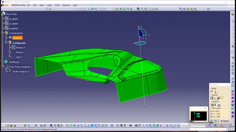
- Displays a color gradient on the faces of selected bodies to help evaluate the manufacturability of your design. Select the bodies to evaluate and the axis to define the direction. Use the options to refine the gradient display. In Catia, we use the feature draft analysis tool for this.
- Select the feature draft analysis tool.
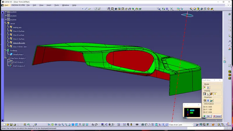
- Then place the compass in the catia on the tooling axis we created. And press the lock symbol appear on the draft analysis window.
- Then place the cursor and click on the model to do the draft analysis.
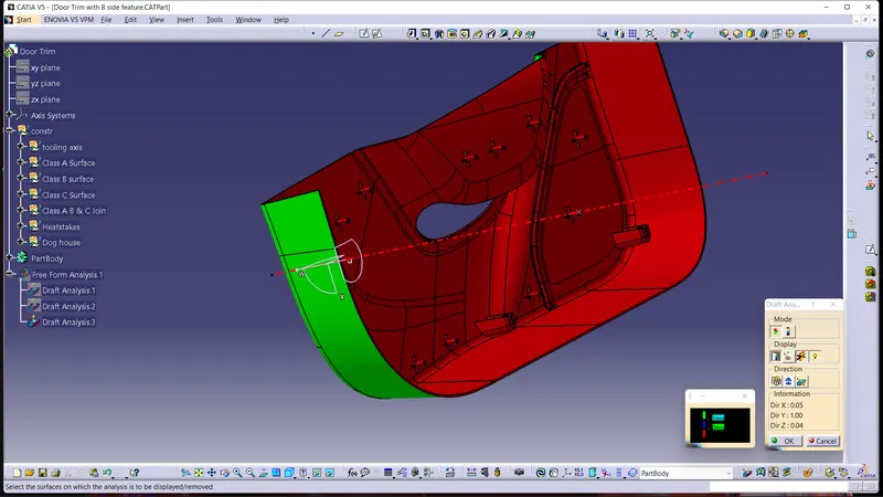
- The color appear on the model will indicate the draft angle given on it.
- Green color indicate the draft angle which is equal to and above the given input angle.
- Red color indicate the draft angle which is below the given input angle.
- Majorly we use draft angle as 3 degree.