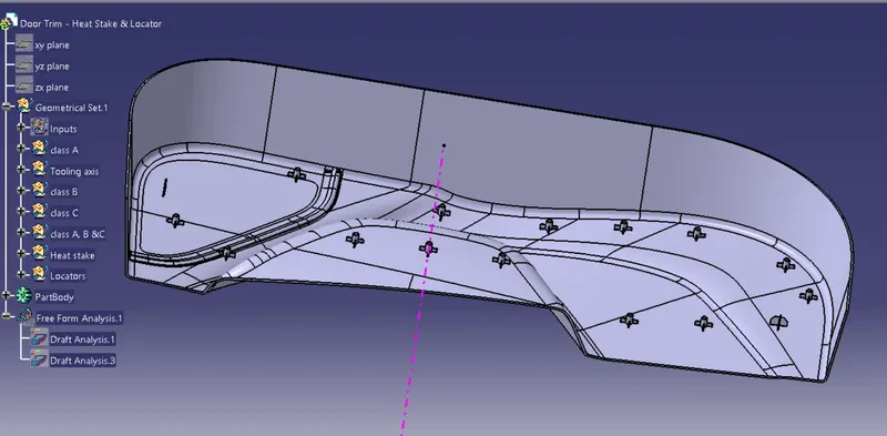
Week 9 - Project 1 - Door Trim Lower with Engineering Features
Objective:
To create the door trim model by using given class A surface by following design considerations and do draft analysis for given class A and final solid door trim model with B featurs.
Procedure:
To create the door trim model by using given class A surface, we have to follow the below steps:
1. Feasibility check
2. Creating the tooling axis
3. Drafting analysis for class A surface
4. Creating the class B surface
5. Creating the class C surface
6. Conversion of closed surface into solid
7. Creating the B side features
8. Final draft analysis for solid model
1.Feasibility check:
A feasibility study, as the name suggests, is designed to reveal whether a project/plan is feasible. It isanassessment of the practicality of a proposed project/plan.A feasibility study is part of the initial design stage of any project/plan. It is conducted in order to objectively uncover the strengths and weeknesses of a proposed project or an existing business. It can help to identify and assess the opportunities and threats present in the natural environment, the resources required for the project, and the prospects for success.
2.Creating tooling axis:
Creating the tooling axis is very important, why because it is used for doing the draft analysis and some times it is used to generate surface while using sweep command. It is also used in creating the B-side features because those are must follow the tooling axis, like these there are somany importances for tooling axis.
we can create tooling axis by the following three methods:
1. Using standard axis like X-axis,Y-axis and Z-axis as tooling
2. Creating the line(tooling axis) normal to surface
3. Creating the tooling axis by using Bi-secting methods
we can create the tooling axis by any one method of above three, but the created tooling axis must suitable for draft analysis.
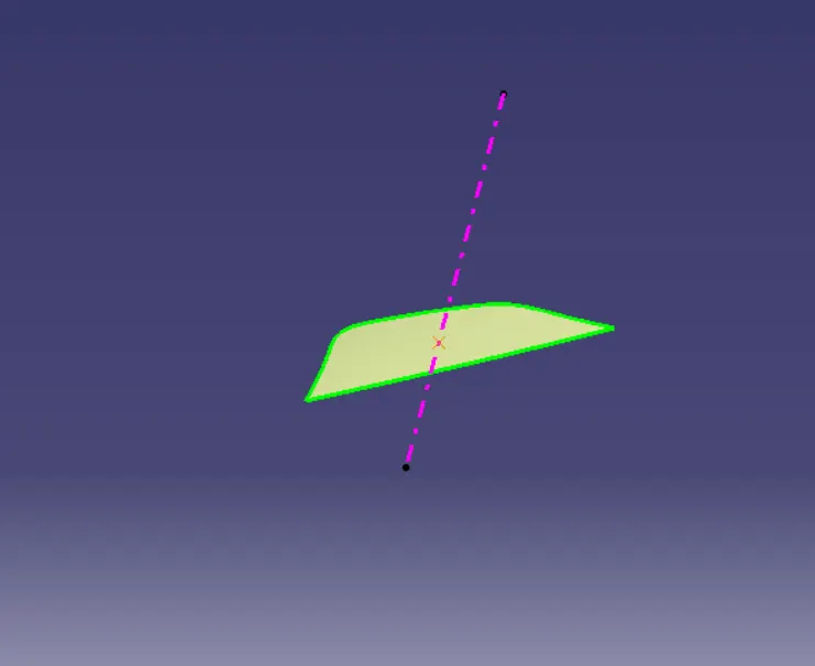
In this model we create the tooling axis by using the method which is creating the line normal to surface which is flat in nature. In this method, first I extract the surface which is flat in nature from class A surface by using the 'extract' command and created the point on the surface by using point on the 'surface command'. And create a line through that point by using the command 'normal to surface'.This line is used as tooling in this model. The following is screensnap of the tooling axis created for this door trim model.
3.Draft analysis for class A surface:
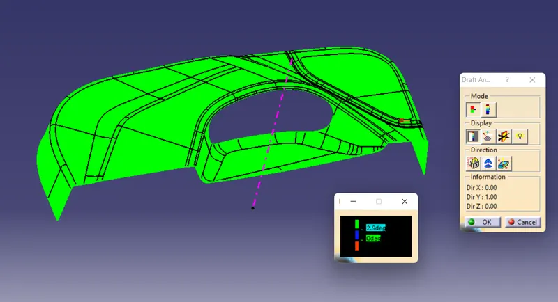
After creating the tooling axis, we should conduct draft analysis for given class A surface. The reason behind doing the draft analysis for the given class A is that checking the class A surface whether it is following the draft angle to the surface which is necessary because without draftangle it is hard to remove the moulded part from the mould and it may cause defects on the surface of part.
To do this firt we have to put view mode into material type and click on the feature draft analysis which is present in the analysis,it is present in the insert option then feature draft analysis dialog box will open.And next bring the compass and place it on the tooling axis and set colour values in display mode as one colour for degree angle between 0&3 , another colour for above 3 degree angle and another colour for the angle below the 0 degree angle. And click on the surface, if the surface colour changes to the colour set for above 3 degree then it means it passed the draft analysis otherwise it means it failed.And in case of failure, we should report to class A created engineer. In this model the class A surface passed the draft analysis test. And the following is the snapshot of the draft analysis of class A.
4.Class B surface:
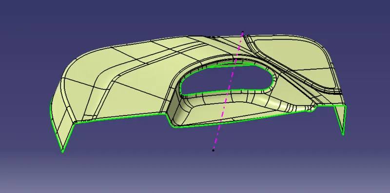
Class B surface means the surface which is not visible to outside after it get assembled or the opposite side surface of class A. We can get the class B surfaces by extracting the class A and do offset the extracted surface upto required length and join those extracted surface and do fillets to required corners by following design considerations. Or we can directly offset the whole class A surface and resolve the problems if generated on class B surface generated.
In this model, I directly offseted the whole class A surface and I get some errors on class B like hole patches means some surfaces not get offseted. Those problems were resolved by using some commands like multisection surface, fill, sweep, extrapolate, join, split and boundary etc., And extrapolate all the boundary surfaces of class B for to happen the intersection between class C and class B. The following is the snapshot of the class B surface created in this model.
5.Class C surface:
Class C surfaace is the surface which joins the class A and class B surfaces. Basically it is thickness of the model. In this model, the class C surface is created by sweeping the surfaces by boundaries of class A surface. we should create the class C surface at draft angle in between 1 degree and 3 degree with respect to tooling axis which is parallel to the tooling axis and create the class C surfaces at 90 degree to the class A when coming the class C is perpendicular to tooling axis. And the following is the class C surface created in this model.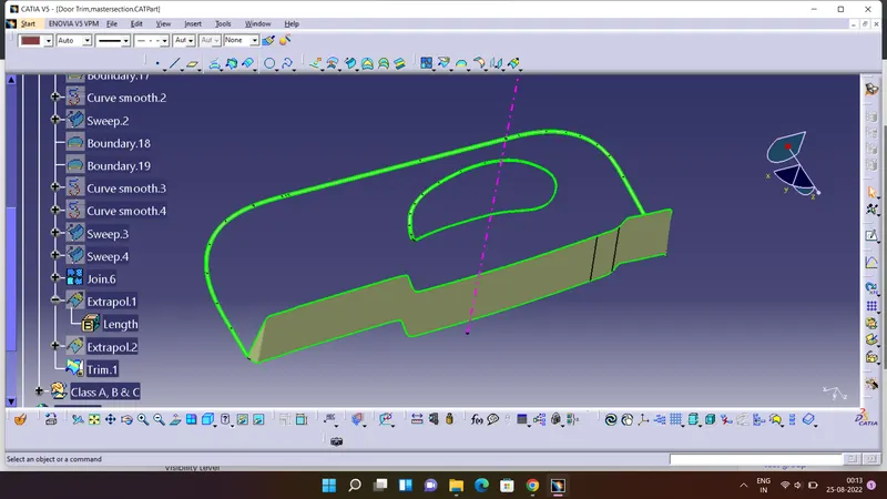
6.Conversion of closed solid into the solid:
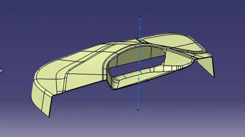
For modelling the solid model, we closed surface of class A,B&C. To get the closed surface of classA,B&C we need to join the class A, class B and class C surfaces by using some commands like join and trim. While joining any surfaces, the merging distance should not be less then the 0.003mm. After creating the closed surface, we should make this closed surface into solid by the command 'closed surface' in part workbench. And the following is the closed surface of class A,B&C.
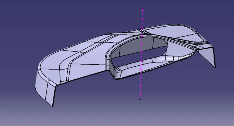
And the following is the snapshot of solid model after converting closed surface into solid in this door trim modelling
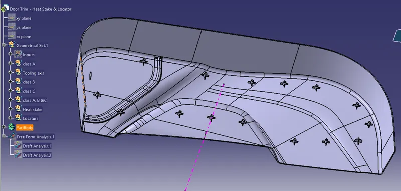
7. Creating B side features:
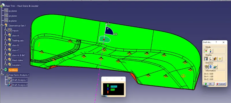
For this model,the B side features are heat stakes and locators, we have to create those according to the input points given by following design rules. And the following screensnap dog house creation.
7.Final draft analysis for solid model:
Same as in the step of draft analysis of class A surface, here also we doing draft analysis to the solid model. And the following is the snapshot of draft analysis of solid model.
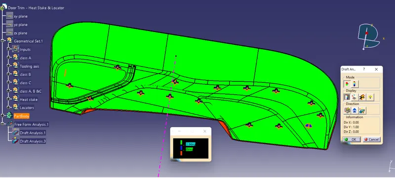
And the following is screensnap of draftanalysis of doghouse
Result:
The creation of door trim model by using the given class A surface and draft analysis for class A and solid model with given B side features is completed.