Week 9 - Project 1 - Door Applique Design with Engineering Features
OBJECTIVE: Create Tooling axis for the given DOOR APPLIQUE CLASS-A surface and carry out Draft analysis to meet the required minimum draft angle for plastic injection molding on both Class-A and final 3D model . Create a B-side Engineering features i.e., 2 way, 4 way locators and heatstakes following the Design rules and carryout Draft analysis for the same.
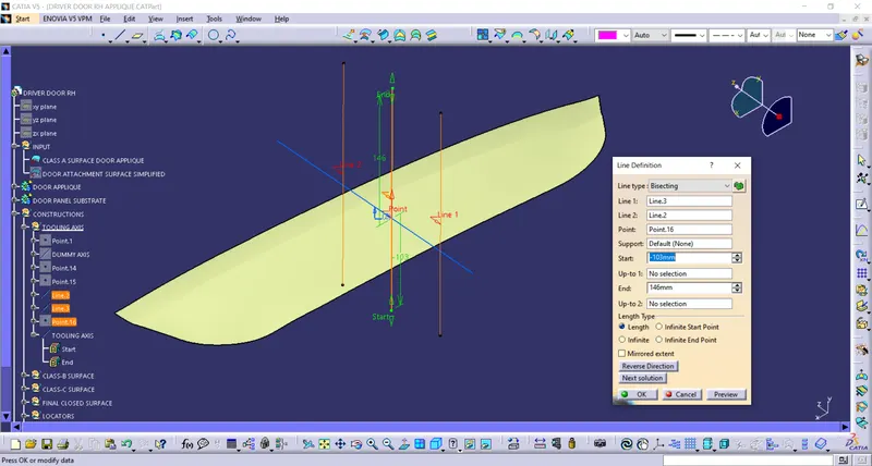
Steps to create Tooling axis:
1. Initial step is to visualise the given input surface carefully so that all the surfaces clears during tooling at one go. While doing this, generally holes, large surfaces with less contours and flat land surfaces are preferred.
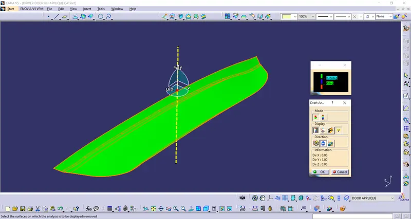
2. There are 3 Axis in a 3D part. i.e., X,Y and Z and 3 planes, XY, XZ and YZ. Two points are created along the curve of the Class-A surface along the Z axis for the particular surface. Two lines are drawn using point to direction method, direction is the Y axis. Now using the two lines created, a bisecting line is created at the mid point of the initial two points created.
Steps to create the Class-B surface:
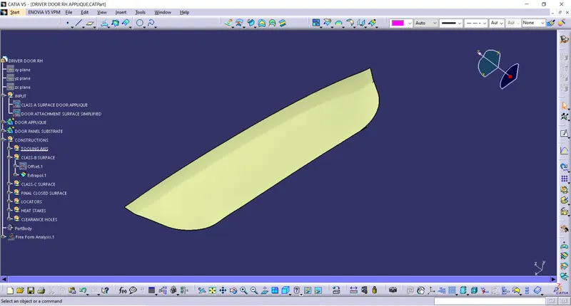
A Simple offset to a value of 2.5mm and extrapolating the surface gives the Class-B surface
Creation of Class-C surface:
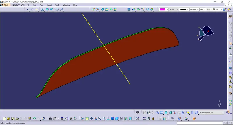
Extracting the boundary of the Class-A and sweeping it to a value larger than the thickness along the Tooling axis to a draft angle of 3 degrees gives the Class-C surface.
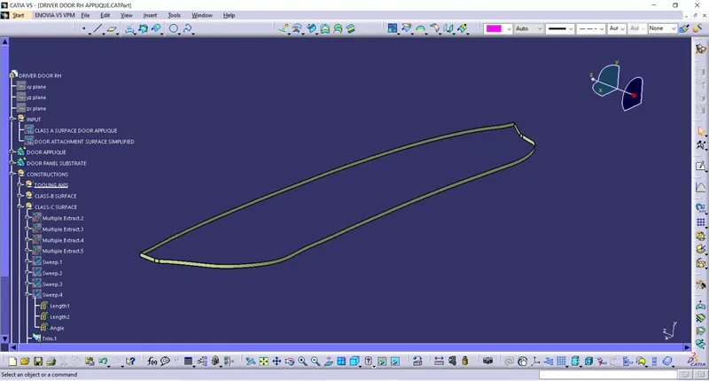
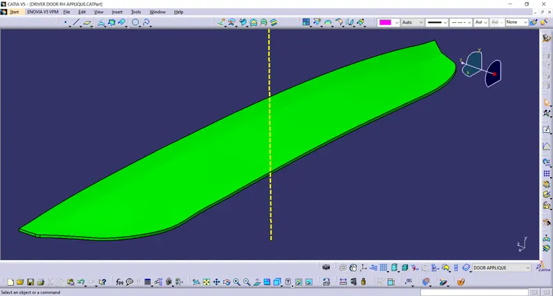
Closed surface that replicates the Final component without B side Engineering features:
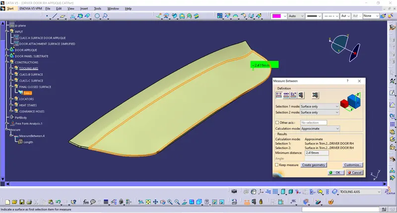
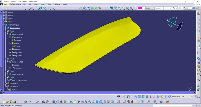
Final closed Solid 3D model:
Creation of B side Engineering features:
Design rules followed to create 2 way and 4 way locators:
- Draft angle= 0.5 degree on all vertical faces
- Thickness of the walls= 1.0+ 0.3 mm (40% of the stock thickness with 30% deviations)
- Top land thickness= more than 0.75mm
- Height= restricted by the top land thickness.
- Fillet radii= 0.25mm optional
- Chamfer and edge radii for easy assembly
Design rules followed for heat stakes:
- Draft angle= 0.5 degree on all vertical faces
- Thickness of the walls= 1.0+ 0.3 mm (40% of the stock thickness with 30% deviations)
- Height= Less than the height created for locators
- Fillet radii= 0.25mm optional
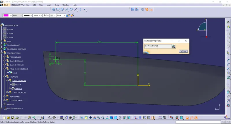
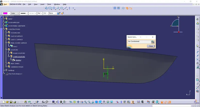
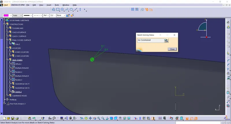
After creating the solid model for one of the features, others are copied, pasted as special, with result with link and translated to the points created along the parallel curves of the final closed surface
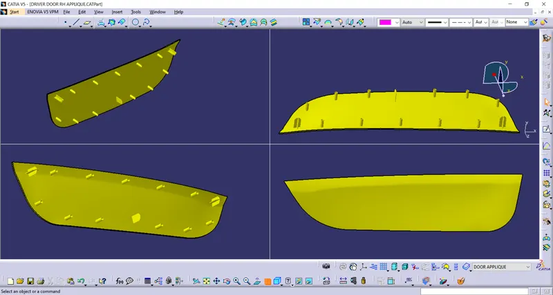
The door panel substrate is being created with the clearance holes with a clearance of 0.1 mm per side for the locators and 0.5 mm per side for the heat stakes, so that the Applique can be assembled to the door trim.
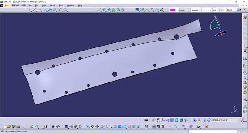
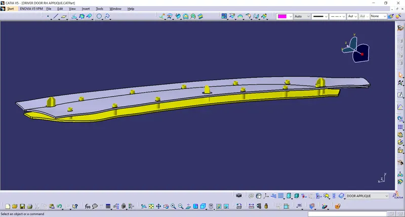
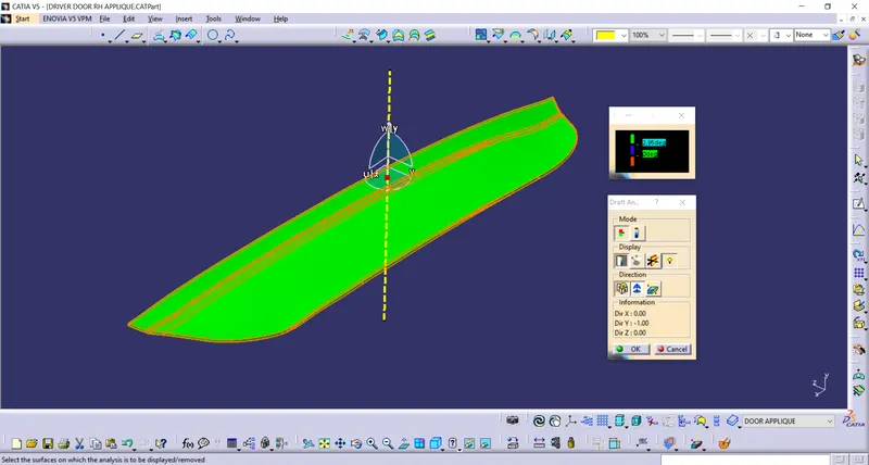
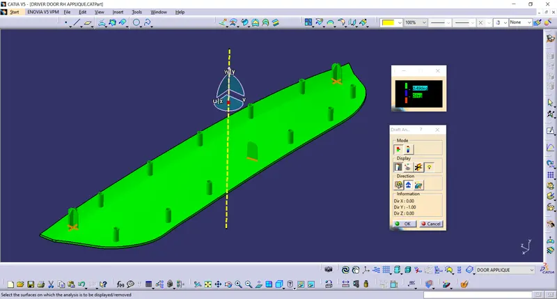
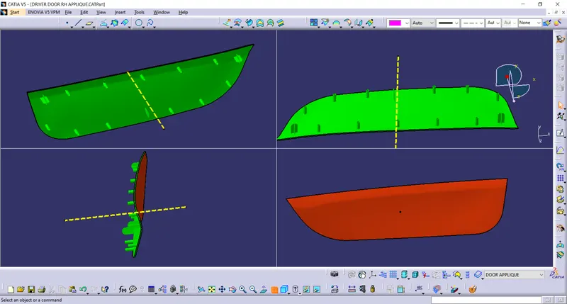
Draft Analysis of Class A and final 3D component: