Week 5
Objective of the challenge: To check Geometrical errors, mesh with given element Quality criteria, and the final model should be free of OFF elements and there should be no kicks or dips in the model.
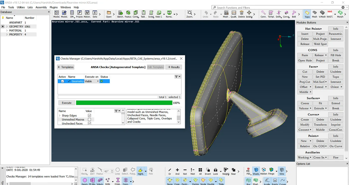
Step 1: To check for Geometrical errors found out by using Checks Manager option in and resolve them using various techniques by panning through various areas/regions where the errors are popped up. The below Image shows that the model is free of Geometrical errors and only procedeeded further after resolving them.
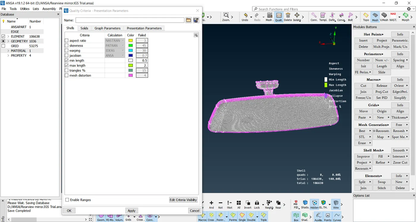
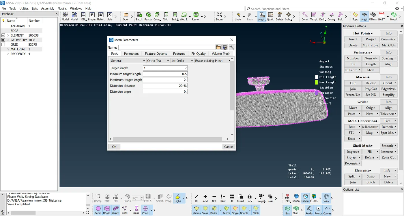
Step 2: The next step is to carefully select the areas/faces that needs to be meshed and to mesh just the outer surfaces. The quality criterias are being entered as such:
|
1 |
Target/Average length |
1 |
|
2 |
Minimum Length |
0.5 |
|
3 |
Maximum Length |
2 |
|
4 |
Tetcolapse |
0.2 |
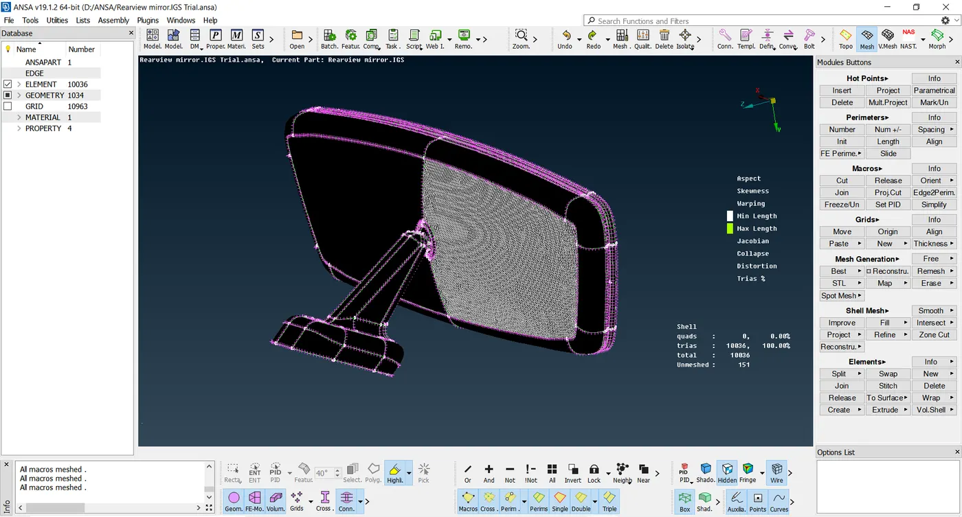
Initially the process of defeaturing nees to be done on the crucial and complex areas. It is advised to use Only Triangular Elements for the solid modelling unlike sheet metal components having 2 parallel surfaces, where a mid surface needs to be generated.Under Under mesh module, Spot mesh using combination of Tria and Ortho Tria Elements. For critical faces, which is having more curvatures and contours, it is advised to use Ortho Triangular Elements so that the elements surrounding the meshed macro region will be intact with the neighbouring meshed macro region. For more of a flat surfaces, Triangular Elements are used. All in all, it is to be ensured that the smooth flow of the mesh is being achieved. The below images depicts the above mentioned steps One by one individually. At the end, it is ensured that there are no OFF elemens in surface mesh
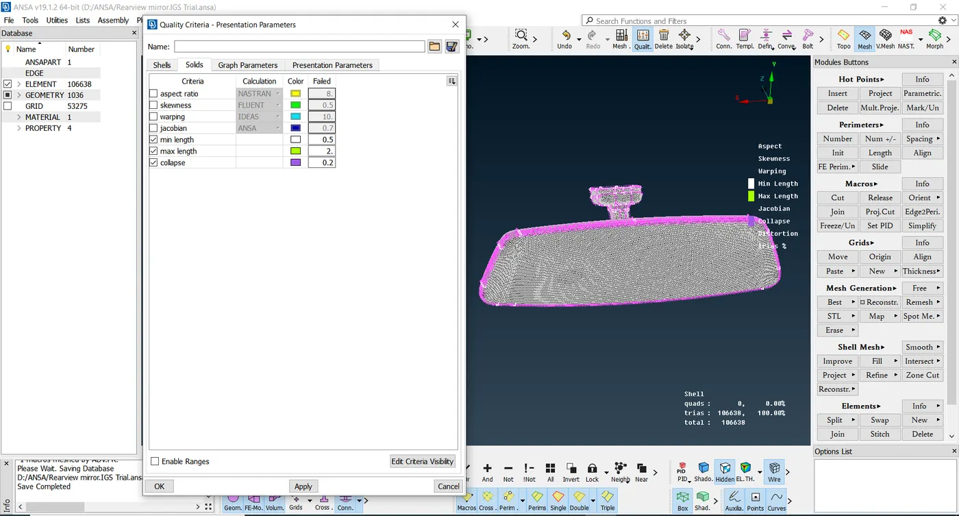
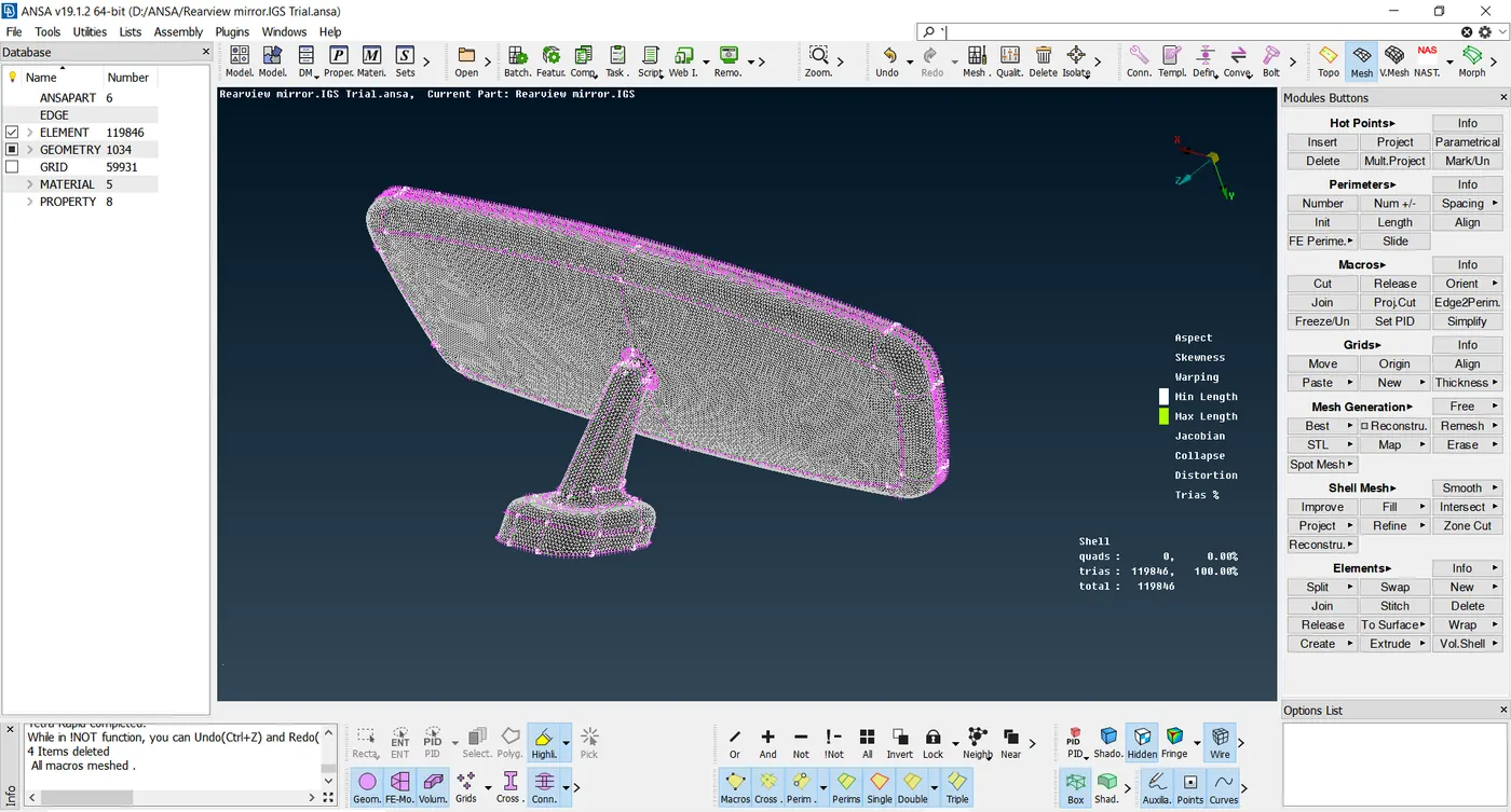
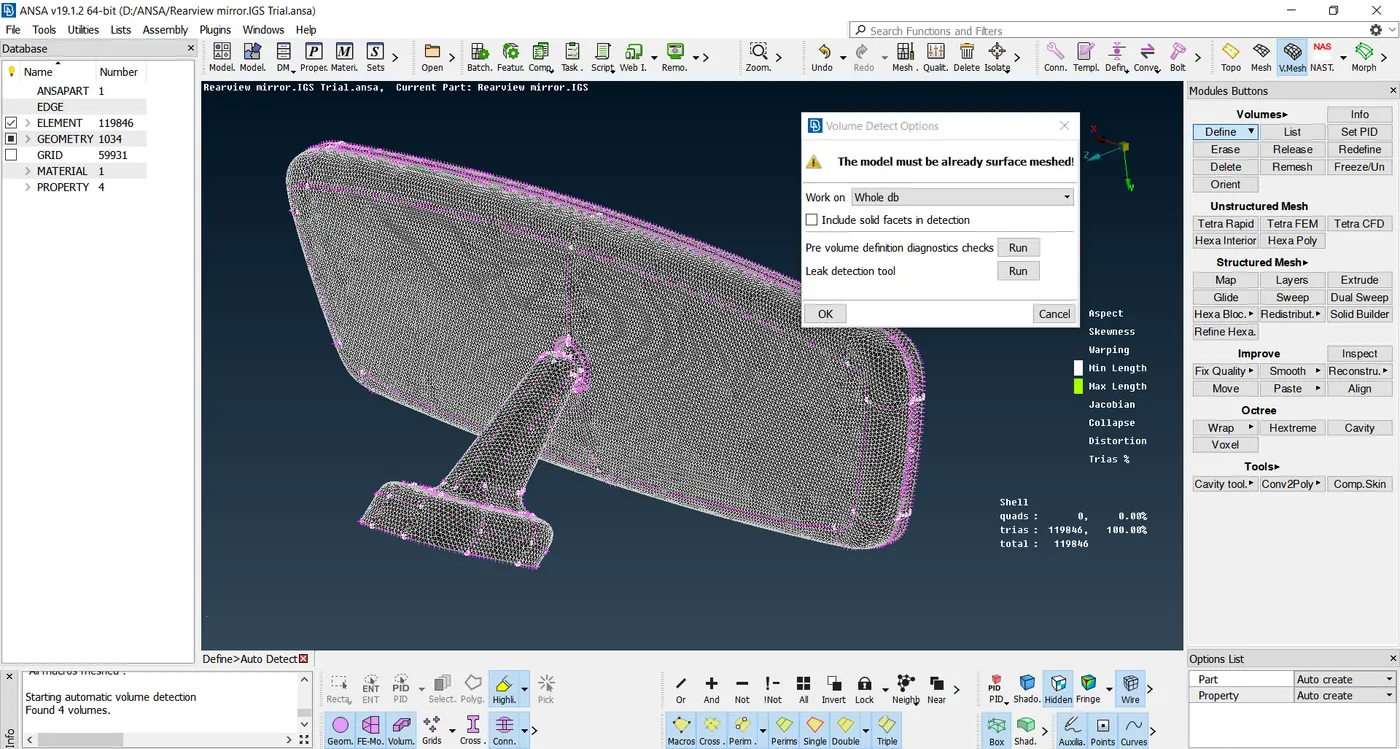
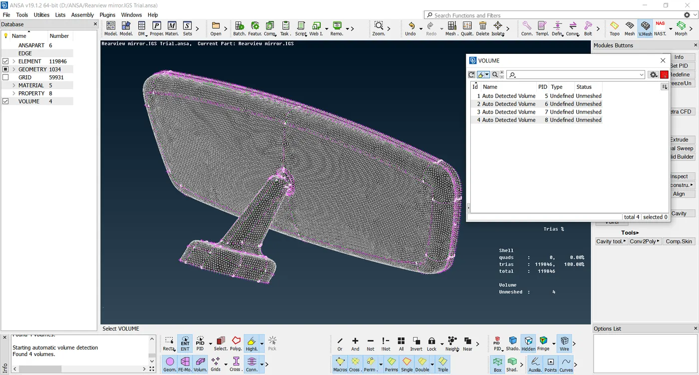
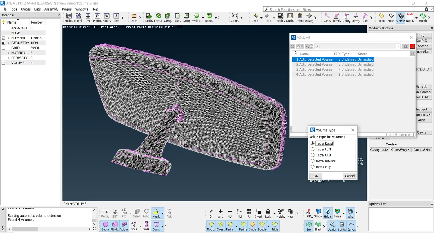
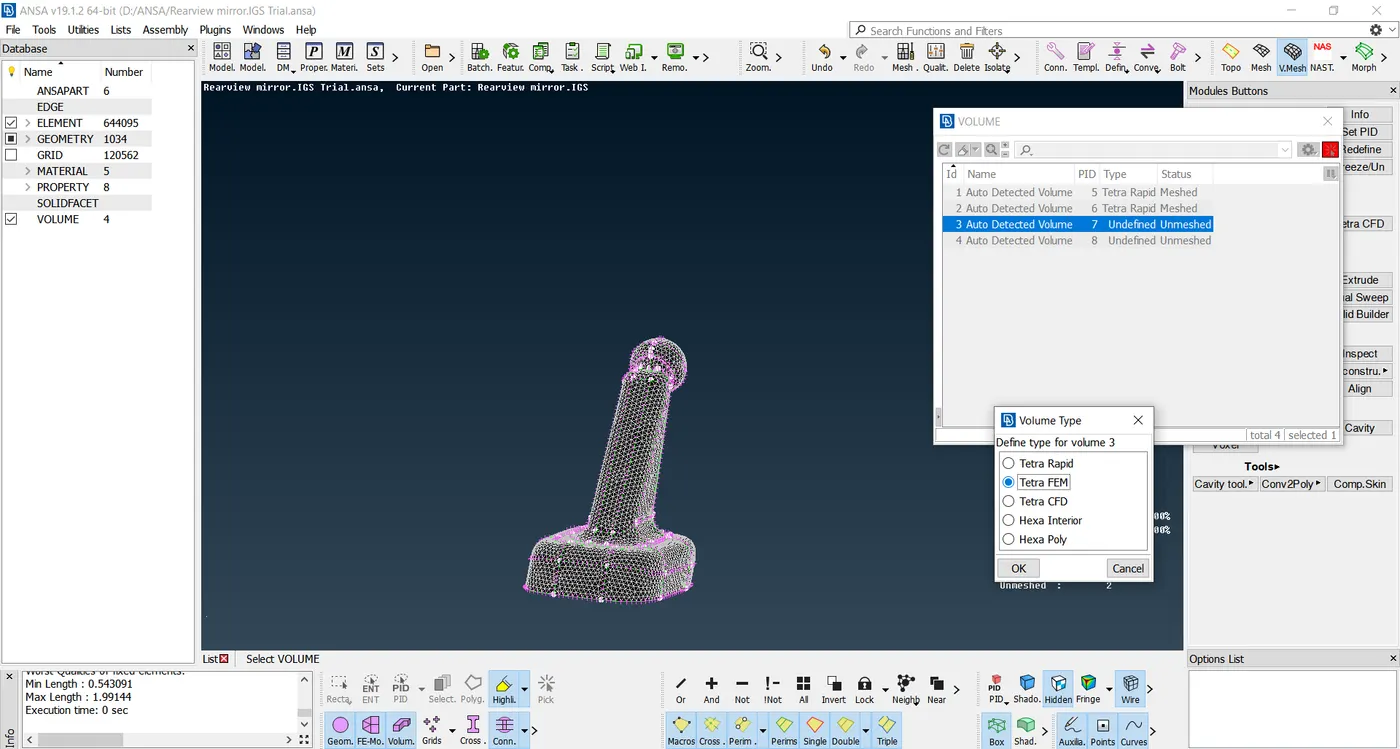
Step 3: The next step is to mesh the inner hollow surface, i.e., Solid Meshing. The steps that are being followed are being explained further, Among this, the first step is the identify the number of solid regions is to move into Volume Mesh(3D Mesh) from Plane Meshing(2D Mesh). It is carried by clicking on Define command in Volumes Module and it is ensured that the "Whole db" is checked, so that entire number of solid regions are being Auto detected. The manual method can also be followed to identify the Volumes, where the time taken is more compared to the previous process. After detecting, the volumes are being meshed using Tetra Rapid or Tetra FEM Mesh one after the other. In this particular model there are 4 volumes that needs to be meshed as shown. After ensuring that the elements are not failing for the defined criteria, the FE model and the CAD Model are being seperated using Release command in Volumes module.
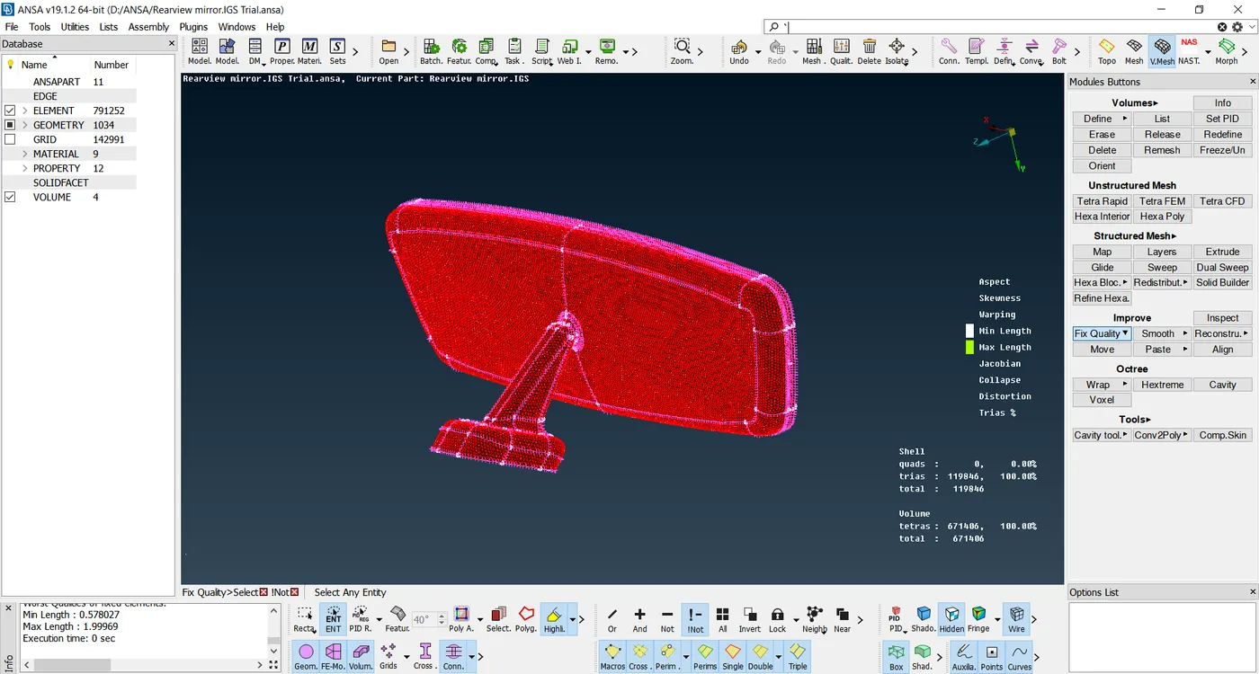
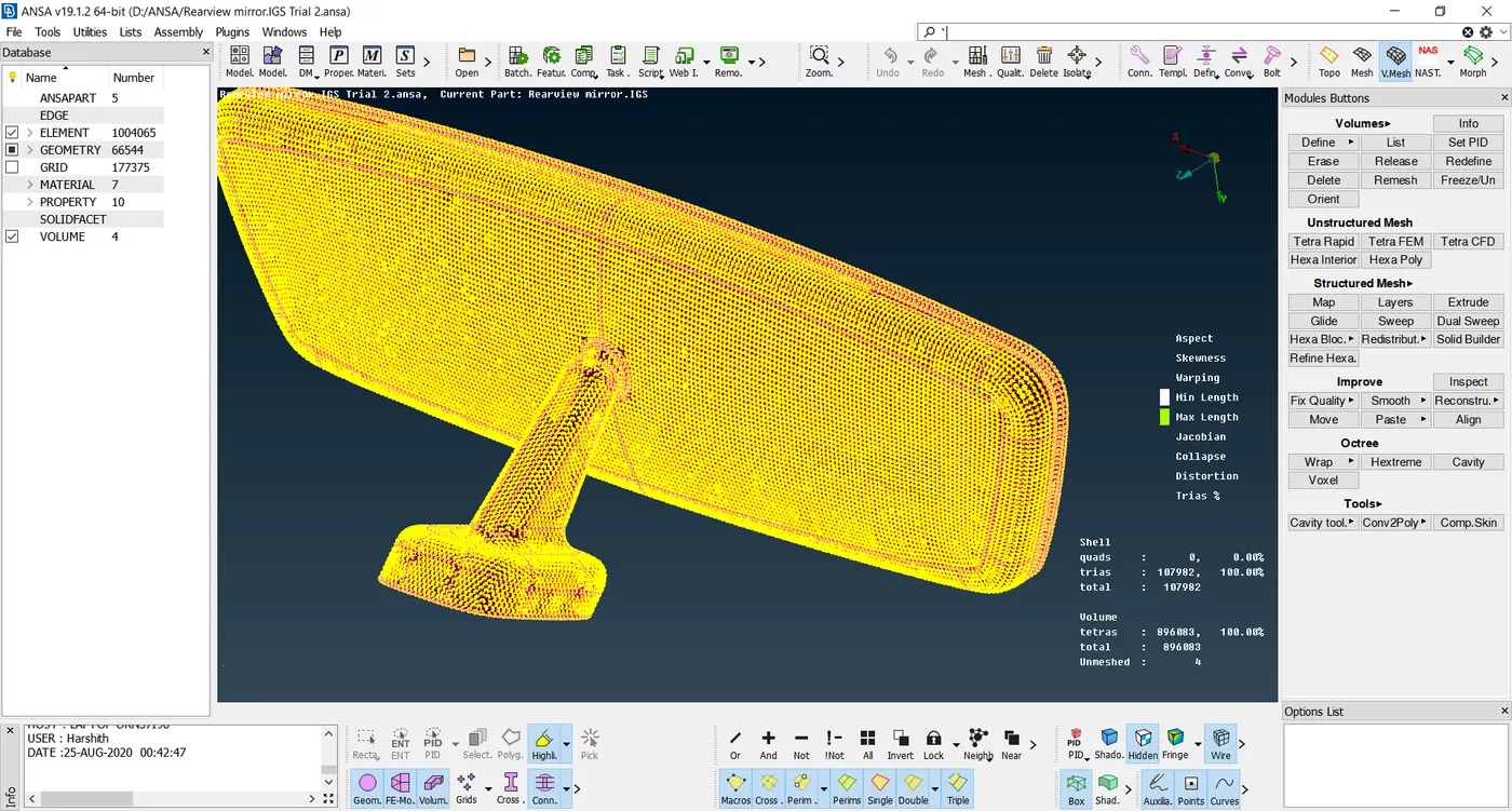
Conclusion: The model is being meshed with the assigned Quality criteria, with no kicks and dips in the meshed surface.
Link for the model: https://drive.google.com/file/d/1W985Y6QTau-caYPLZoA-69chfJEF3rM5/view?usp=sharing