Week 9 - Project 1 - Door Applique Design with Engineering Features
AIM
To Create the Heat Stakes and the locators considering the design rules mentioned in the video for the door applique by using catia v5
SOFTWARE USED
CATIA V5
DRAFT ANLAYSIS
Draft analysis in catia is a command that is used to detect if the part you drafted will be easily removed from the mold. it is performed based on color ranges identifying zones on the analyzed element.
Most of the industries is using minimum draft angle is 3 degree
PROCEDURE
- Check all the boundary whether it has connected or not.
- Check the model visually & choose the best tooling direction which should be easy for draft.
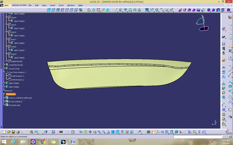
- After analyzing the above model the best tooling axis is y direction.
CREATING THE TOOLING AXIS
- Measure the surface using measure inertia and create a centre of gravity point.
- offset a zx plane to that point
- create a line using point direction as a direction of y and named as TOOLING AXIS as shown below
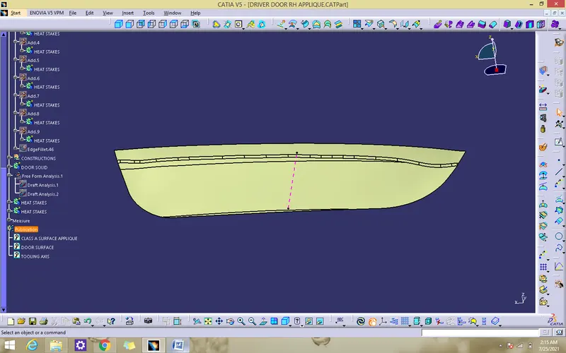
PERFORMING DRAFT ANALYSIS ON MODEL
- To perform draft analysis open customize view parameters and choose the material
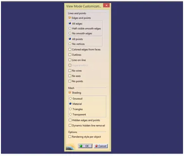
- Insert a feature draft analysis by following these commands
I insert>analysis>feature draft analysis
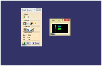
- Align the compass on tooling axis that we created
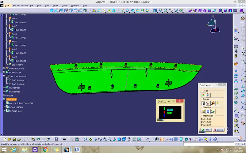
- Open the color scale and enter the value is 0.4 deg.
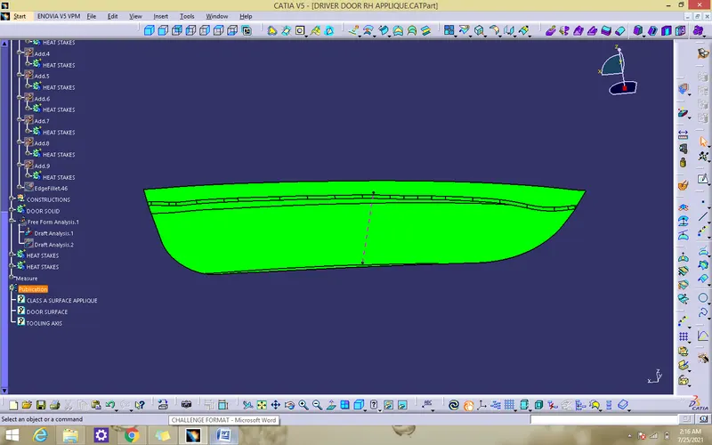
- If the whole body is green that all the faces is greater angle than the provided angle
DRAFT ANALYSIS REPORT OF CLASS A
DRAFT ANALYSIS REPORT OF SOLID MODEL
CREATION OF LOCATOR
- Extract the surface that we going to create a locator
- use positioned and draw a locator sketch
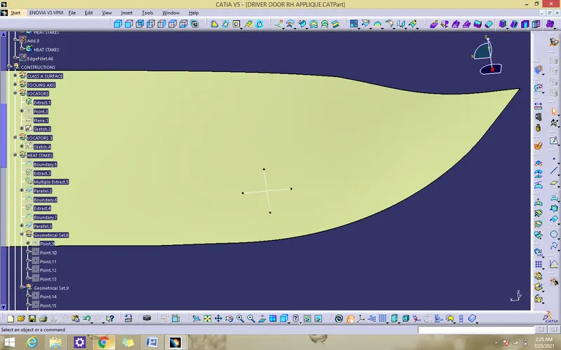
- Use pad command the sketch to till we required
- Draft the locator of minimum of 0.5 degree
- chamder the locator for 3mm
- Add fillet 0.25mm to all faces
- Assemble the locator to applique solid
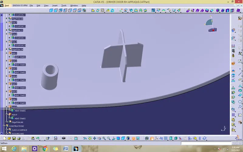
CREATION OF HEAT STAKES
- Extract the surface that we going to create a heat stakes
- use positioned and draw a heat stakes sketch
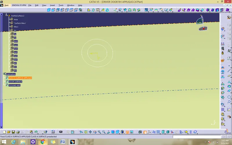
- Use pad command for the sketch to till we required
- Draft the stakes minimum of 0.5 degree
- Add fillet 0.5mm to all faces
- Assemble the stakes to applique solid
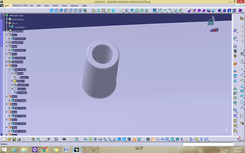
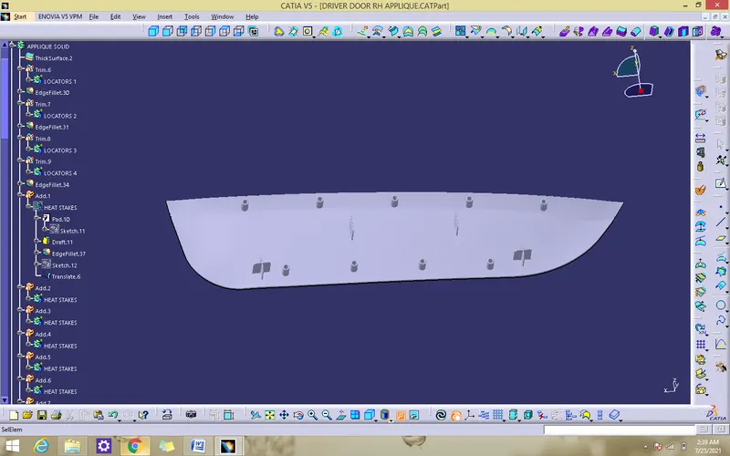
- extract the class a surface boundary.create parallel curve for that boundary towrads inward
- create a multiple point for 50mm
- create a heat stakes by following above method
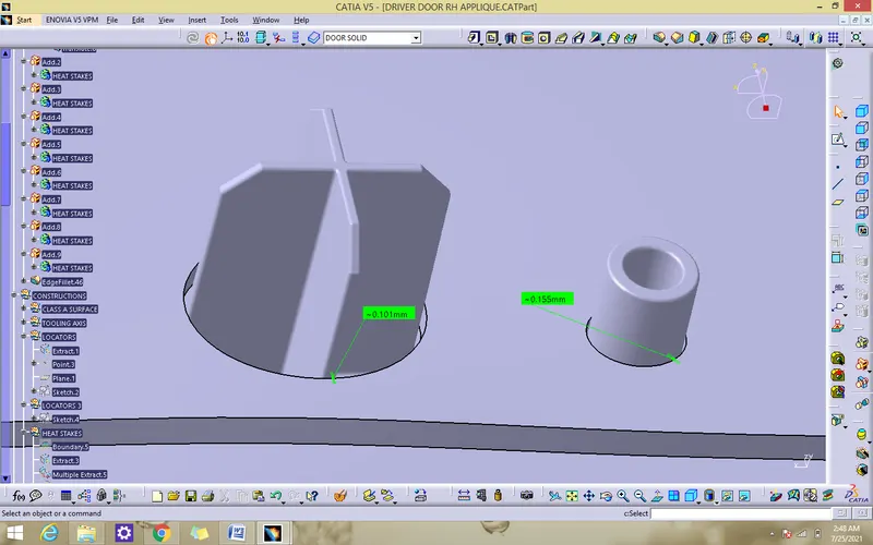
CREATE A CUTOUT IN DOOR SURFACE
- Create a cutout for all heatstake and locators for nearby 0.1mm to place the applique on door surface
MODEL IN VARIOUS ORIENTATION
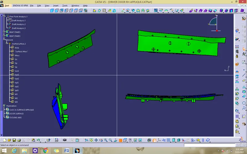
CONCLUSION
Thus the 3D model has been created using catia v5.