Attachment Feature Creation for Applique Model in Driver Door Panel
APPLIQUE MODEL CREATION
The aim of this project is to create a Product Developed from Class A surface and create Attachment features for the part to locate and fix with the mating part
ABSTRACT
The report details about the creation of Applique model which will be fixed on the RH Door Panel. The report explains the steps followed in creating the tooling axis followed by detail methods in creating B-Surface and developing attachment features on the B surface. The Attachment features are created based on 3-2-1 Taylors Principle.
DESCRIPTION
APPLIQUE
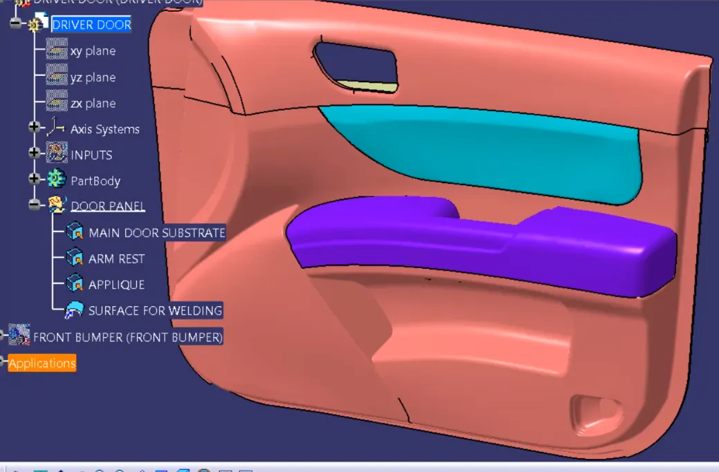
Applique part is an asthetic part that is attached on the Interior Door Panel Substrate. The part thickness is 2.5mm which is an ideal thickness for plastic injection molding. The B Side feature creation are carefully designed based on the rules to avoid plastic defects on the A surface.
The Door Panel usually has following parts
- Door Panel Main Substrated Mold
- Arm Rest Bezel
- Applique
FIXATION FEATURES
Fixation features are used to position the mating part and align the part. The Fixation parts are
- Ribs
- Dog House and Screw Boss
- Two Way and Four Way Locator
- Heat Stakes
The Fixation Features used in Applique part are two way and four way locator and Heat Stakes
HEAT STAKING
Heat Staking is plastic welding process that fixes parts permanently on to the main substrate.
A Plastic stud is melted and reformed which protrudes through the hole and locks the component
The main advantage is multiple fastening points are provided with simple machinery requirements at reduced cost compared to hot air cold form or UV 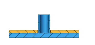
TWO WAY and FOUR WAY LOCATORS
The two way and four way locators are used to constrain the translation and rotation of parts in the assembly.
They follow 3-2-1 Taylor Principle which is used to locate the fixation of parts and arrest the degrees of freedom
Every part has 12 degrees of freedom
Translational Movements along X,Y,Z Axis ( Positive and Negative)
Rotational Movement along X,Y,Z Axis ( Clockwise and Anticlockwise)
The parts to be welded should or fixed should constrain these motions
The Four way and two way locators facilitates the above process.
They are usually provided at three very extreme of component based on the mating direction and surfaces.
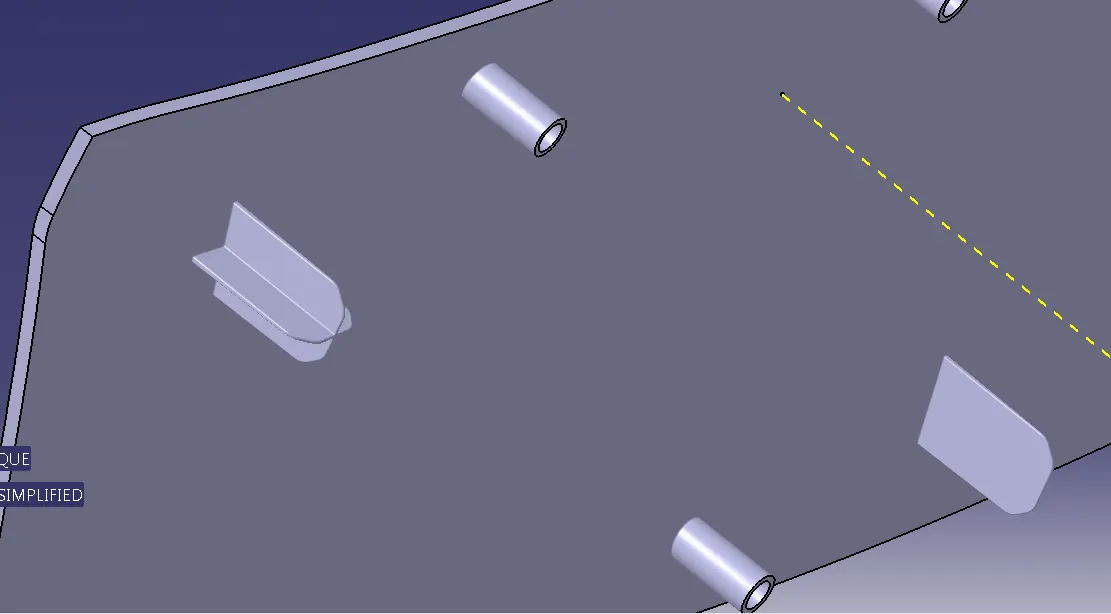
The fixation features are shown above
DESIGN PROCEDURE
The Class A input obtained is used to create the closed part by following the methods below
TOOLING AXIS
The given Class A input is analyzed to envision the part to manufacture and Tooling axis or Tooling Direction or Die line is the direction that molds pull apart in injection molding. There are two mold pieces names core and cavity. Thus tooling direction determines Mold separation and also becomes vital in developing the plastic product drafted to desired nominal angle for feasible clearance and ejection of final part from the mold.
The Steps Followed in creating Tooling Axis
- A Reference Point is created along the Surface zero and new Axis system is created
- The X Direction along the Class A and Y direction along the Class A were used to create Tooling direction
- Finally the Tooling axis is created by bisecting the two lines and it is published. Class A Surface as input using surface operation commands Class B is developed
- The tooling Axis determines the direction of Class C boundary swept with draft direction.
- When viewing from tooling direction normal all the parts that are drafted should be visible so it gives an rough idea to determine product manufacturing in Injection molding
SURFACE CREATION
Using Class A Input the surface is extracted ,extrapolated and offset to 2.5mm and the C surface is formed which is drafted along the Tooling Direction using sweep with reference surface and guide curve and a closed surface is formed which is developed to form part model in part design workbench
The Attachment features will be created on the B Side of the part which is not visible.
DRAFT ANALYSIS
The Draft Analysis is done to measure the drafted value of the component. The Ideal Draft angle for plastic part is 3 degrees and the ribs are provided with 0.5 degree draft on both sides.
- The Green color is drafted walls above 2.9 degree
- The Blue color is drafted walls from 0-2.9 degree
- The red surfaces are negative degree
- The analysis shows the drafted walls are above the par of 2.9 degree which is permissible to manufacture in the injection modeling.
- The Running point analysis hovered along the drafted walls show all parts are drafted and and will be easily cleared from ejection.
- Finally the part is used to define further fixation creatures and support structures to pass on to manufacturing process
ATTACHMENT FEATURES
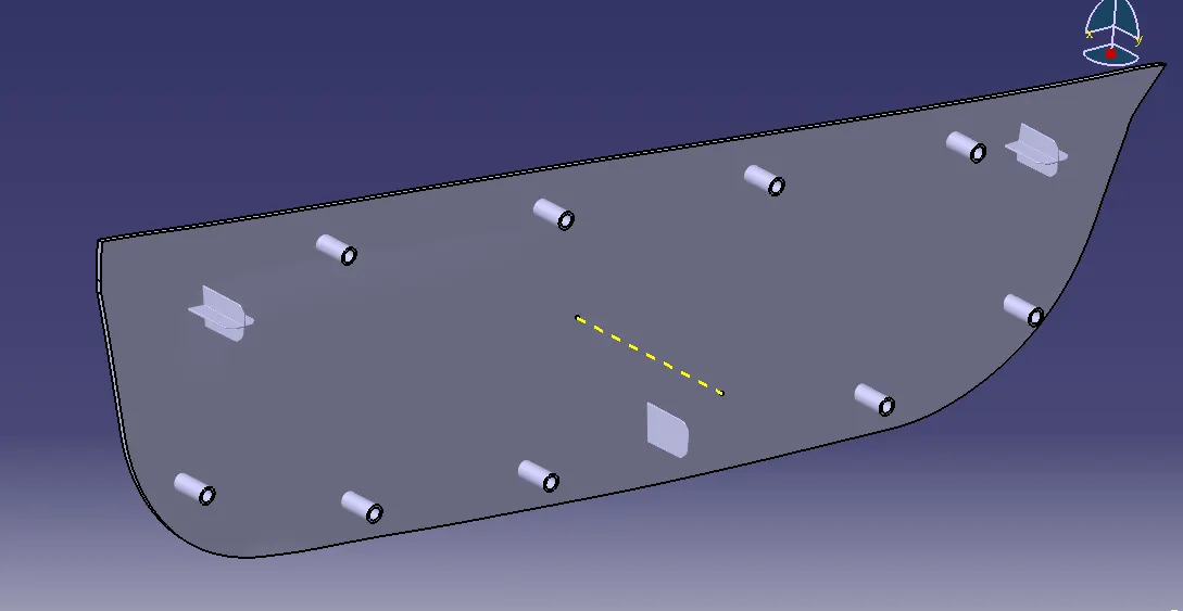
The Applique part has two 4 way and one two way fixtures that constrains 11 degrees of freedom. The only persmissble freedom is mating direction along Y which will be fixed using heat stakes and thus all 12 dof are controlled
DESIGN RULES
The Design Rules for two way and four way fixtures are
Rib Wall Thickness should be 0.4 times of Thickness of the part
The Drafted walls of rib should be within 0.5 degrees
The top height of rib should be at least 0.70 mm thick to allow the molten plastic to reach the top
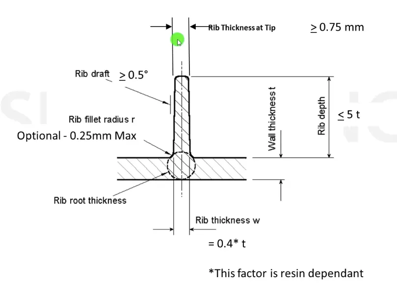
- The height of the locators should be on same plane and should be well attached to the part.
- An entry chamfer is provided on the top to provide the feasible fixation mechanism
- The locators are added to the main part using Boolean operation
- The Heat stakes should be provided along the boundary at variable fastening locations and the height of heat stakes should be lower than the locators.
- Using parallel curves and pattern point along the curve suitable heat stakes are developed and ensured that they are not interfering with Locators.
- The Locators and heat stakes are drafted min 0.5 degree along the neutral face
- A sample attachment door substrate is developed using Class A surfacing methods and then clearance for the part is cutout to provide the entry of locating features.
- A minimal clearence of 0.1 mm is ensured for locating features and 0.5 mm is desired for heat stakes
- Finally the Heat stakes are welded and the mating parts are fixed
- The Design Rules followed ensures that plastic defects produced aftermath manufacturing are avoided to improve the quality of the part.
TREE STRUCTURE
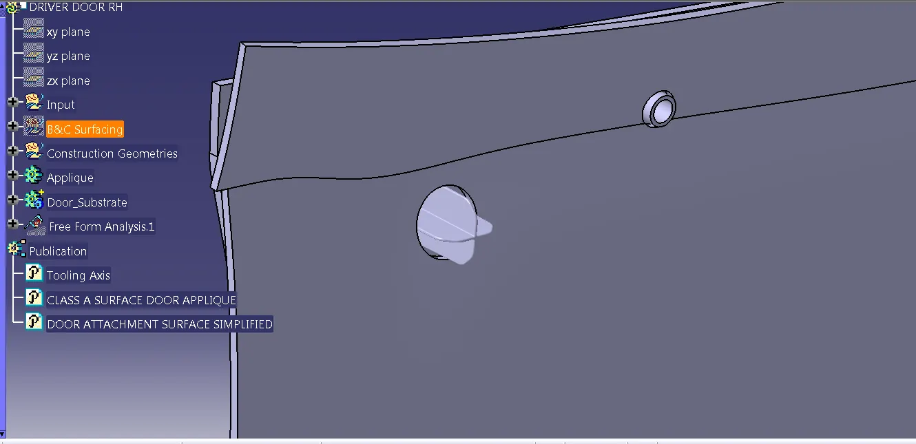
The Classified Tree Structure with seperate Geomteric Sets for different operations and all the sketches are fully constrained
CONCLUSION
Thus a Applique part is developed from Class A Surface and the fixation features are developed along the B side.
The Tooling Axis is created and Class b, Class C are extrapolated and trimmed to form closed body surface and Draft analysis is performed to validate the drafted walls within limits and Attachment features are created carefully adhering to the Design guidelines.