Week 9 - Parametric study on Gate valve.
Aim: To perform a parametric study on the gate valve simulation by setting the opening from 10 % to 80%.
- Obtain the mass flow rates at the outlet for each design point.
- Calculate the flow coefficient and flow factor for each opening and plot the graph.
- Discuss the results of the mass flow rate and flow coefficient.
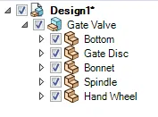
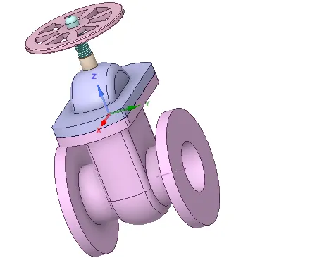
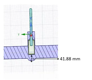
Geometry Simplification :
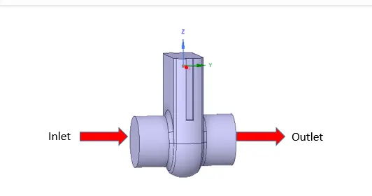
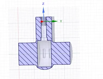
Extraction of fluid volume
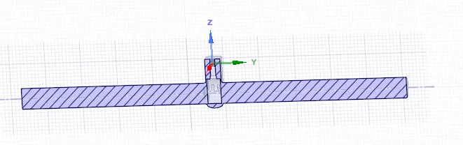
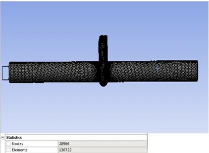
Problem Setup:
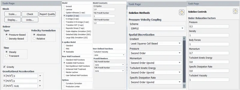
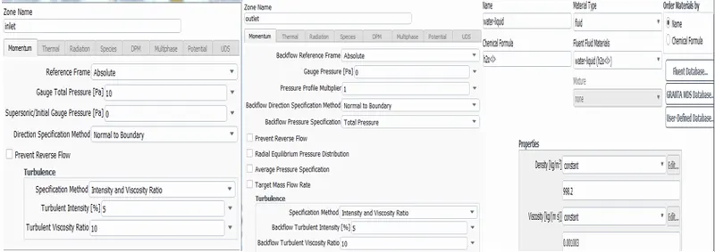
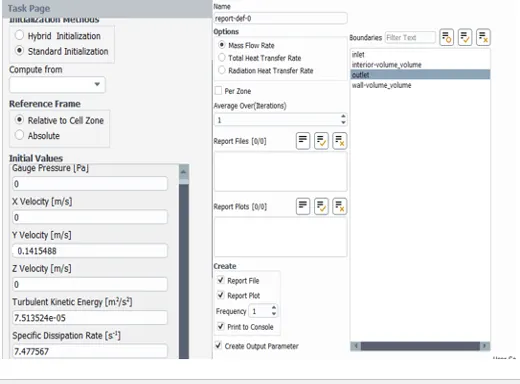
For Pipe flow simulation
Calculating Reynold's number to check whether flow is turbulent or laminar
As velocity is known i.e 0.1415 m/s
Re=998.2*0.1415488* 0.1 /0.001003
=140871.1398
As Reynold's number is more than 2000,flow is turbulent
Case 1 :
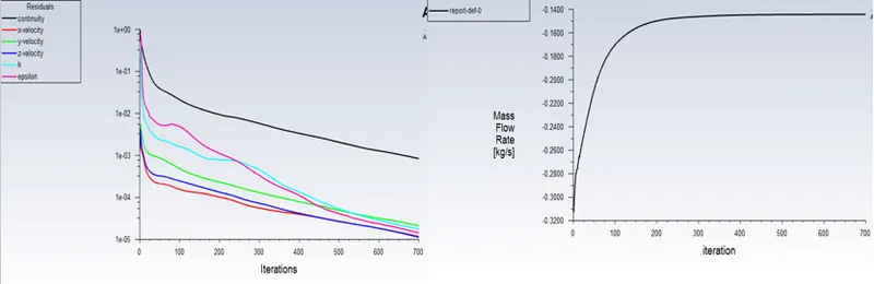
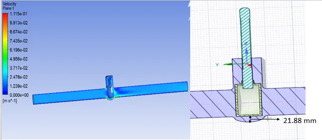
Case 2: 20 mm
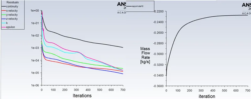
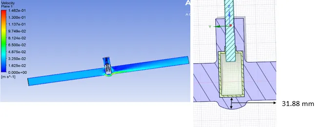
Case 3: 30 mm
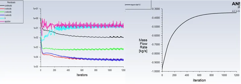
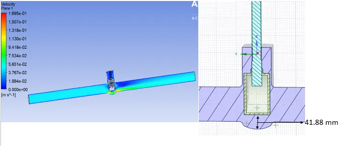
Case 4: 40 mm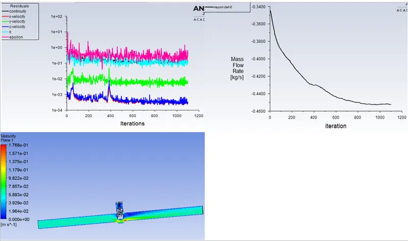
Flow Coefficient
The flow coefficient of a device is a relative measure of its efficiency at allowing fluid flow. It describes the relationship between the pressure drop across an orifice valve or other assembly and the corresponding flow rate.
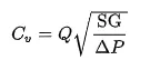
Mathematically the flow coefficient Cv (or flow-capacity rating of valve) can be expressed as :
where:
Q is the rate of flow ,
SG is the specific gravity of the fluid (for water = 1),
ΔP is the pressure drop across the valve
Flow Factor
Kv is the flow factor

Results:

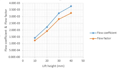
Mass Flow rate Vs Flow Coefficient
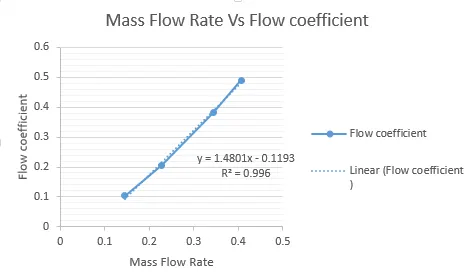
As mass flow rate increases with increase in gate valve opening height, flow coefficient increases.For a opening of 40 mm the mass flow rate and flow coefficient is maximum.