Week 9 - Parametric study on Gate valve.
OBJECTIVE:
To perform a parametric study on a gate valve simulation by setting the opening from 10 % to 80%. To simulate the flow of fluid through a gate valve and obtain the mass flow rates at the outlet for each design point. calculating the flow coefficient and flow factor for each opening and plot the graph.
THEORY:
Gate Valve:
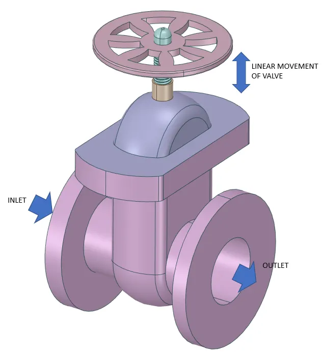
A gate valve, also known as a sluice valve, is a valve that opens by lifting a barrier (gate) out of the path of the fluid. Gate valves require very little space along the pipe axis and hardly restrict the flow of fluid when the gate is fully opened. The gate faces can be parallel but are most commonly wedge-shaped (to be able to apply pressure on the sealing surface).
Types:
- Slab
- Expanding
- Wedge.
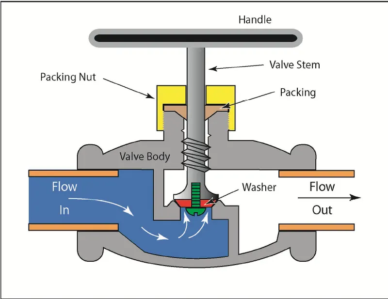
Common gate valves are actuated by a threaded stem that connects the actuator (e.g. handwheel or motor) to the gate. They are characterized as having either a rising or a non-rising stem, depending on which end of the stem is threaded. Rising stems are fixed to the gate and rise and lower together as the valve is operated, providing a visual indication of valve position. The actuator is attached to a nut that is rotated around the threaded stem to move it. Non-rising stem valves are fixed to, and rotate with, the actuator, and are threaded into the gate. They may have a pointer threaded onto the stem to indicate valve position since the gate's motion is concealed inside the valve. Non-rising stems are used where vertical space is limited.
Uses:
- Gate valves are used to shut off the flow of liquids rather than for flow regulation. When fully open, the typical gate valve has no obstruction in the flow path, resulting in very low flow resistance. The size of the open flow path generally varies in a nonlinear manner as the gate is moved. This means that the flow rate does not change evenly with stem travel. Depending on the construction, a partially open gate can vibrate from the fluid flow.
- Gate valves are mostly used with larger pipe diameters (from 2" to the largest pipelines) since they are less complex to construct than other types of valves in large sizes.
- Gate valves without an extra sealing ring on the gate or the seat are used in applications where minor leaking of the valve is not an issue, such as heating circuits or sewer pipes.
- Generally in pipelines with high pressure, the gate valve opening can be quite difficult due to the high force exerted on the gate. So they are generally connected with a smaller bypass valve to release the pressure and then they are operated.
Operation:
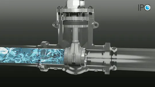
A gate valve operates similar to other valves. To open the valve, turn the handwheel, which moves the gate up or down on the stem via the threads. A gate valve requires more than one 360° turn to open or close the valve fully. When the gate is lifted up, it opens the inlet to the outlet allowing an unobstructed passageway for the media to flow. When the gate is lowered, it closes and blocks the media flow.
Flow Coefficient:
The flow coefficient of a device is a relative measure of its efficiency at allowing fluid flow. It describes the relationship between the pressure drop across an orifice valve or other assembly and the corresponding flow rate. Mathematically the flow coefficient Cv (or flow-capacity rating of the valve) can be expressed as:
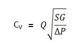
In more practical terms, the flow coefficient Cv is the volume (in US gallons) of water at 60 °F that will flow per minute through a valve with a pressure drop of 1 psi across the valve. The use of the flow coefficient offers a standard method of comparing valve capacities and sizing valves for specific applications that are widely accepted by the industry. The general definition of the flow coefficient can be expanded into equations modeling the flow of liquids, gases, and steam using the discharge coefficient.
Flow Factor:
The metric equivalent flow factor (Kv; commonly used in Europe and Asia) is calculated using metric units:
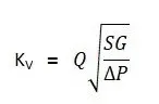
Kv can be calculated from Cv using the equation as given below:
The Kv factor of a valve indicates "The water flow in m3/h, at a pressure drop across the valve of 1 kgf /cm2 when the valve is completely open.
GEOMETRY:
FLUID VOLUME EXTRACTION
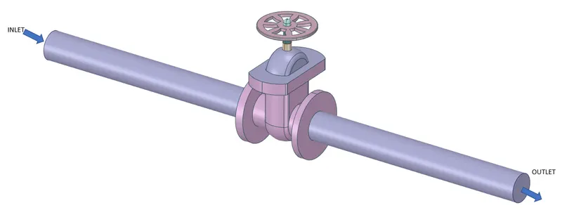
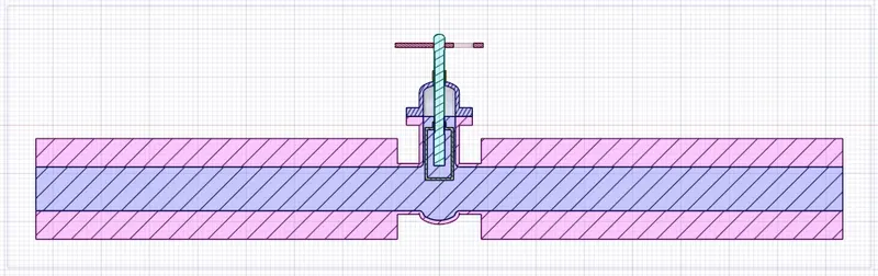
The fluid volume changes as the gate valve lift changes. For this, the verticle movement of the valve is parameterized.
After importing Geometry, hide the “Bottom” Part, so we can clearly see the “Gate Disc”.
- Then Select the “Gate Disc” component and move it in an upward direction by “10 mm” lift.
- To analyze the flow and its effects, we must allow the flow, and for that, we have given the 10 mm lift to the Gate Disc.
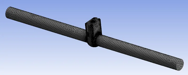
MESHING:
Details:
- Element Size: 5 mm
- of Elements: 597178
- of Nodes: 119029
- After Meshing, update it for further process and go for the Fluent Setup.

SETUP:
- Here we have taken Pressure for inlet = 10 Pa.
- In the Viscous model, we have taken the K-Epsilon model.
- The reason behind choosing the K-Epsilon Viscous model is characteristic of the flow, which is turbulent.
- For Reynolds No. about 2000 and more, flow is turbulent. So we have taken the K-Epsilon Viscous model.
- But here, we have given Pressure Inlet, instead of Velocity Inlet. So knowing the velocity of the flow for correct Reynolds No. is required.
- So, to know the velocity of the flow, we have to go for initializing the solution.
- So, go to Solution, and select Standard Initialization, and Initialize from Inlet.
- After initialization, we can get the correct velocity and calculate the Reynolds No. and from that, we can decide on the appropriate viscous model.
Geometry
- Solver - Pressure Based
- Time - Steady State
Model:-
- Viscous - K -Epsilon (Realizable - Scaleable Wall Function)
Material:-
- Fluid - Water
Boundary Condition:-
- Inlet - Pressure Inlet ( Gauge Pressure - 10 Pa)
Method:-
- Scheme - Coupled
- Initialization - Standard from Inlet
- Number of Iteration - 300
PARAMETRIC STUDY
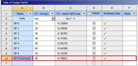
In the above image, the Parameterization of the valve to increase the flow area is given. The parameters are set for the study of different design points of the lift of the gate valve. On completion of the simulation, select “Parameter Set” and give input for different Design Points. Then Update all Design points and check all the results of different Design points.
Results:
Cases of lift of “Gate Disc” from 10% to 80% one by one.
- for all types of results, calculate the Flow coefficient and Flow Factor accordingly.
- Mass Flow Rate at Outlet, Flow Coefficient and Flow Factor and required Plots for each opening.
Cases:
Here we will discuss all cases according to the opening percentage of “Gate Disc”.
According to the opening of the valve, given as lift of “Gate Disc” in mm, all 8 cases are named as given below:
- Case 1 = 10
- Case 2 = 20
- Case 3 = 30
- Case 4 = 40
- Case 5 = 50
- Case 6 = 60
- Case 7 = 70
- Case 8 = 80
Case 1: Gate valve lifted by 10 mm
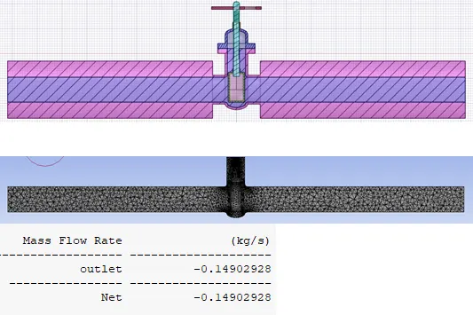
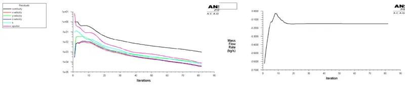
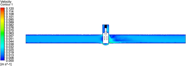
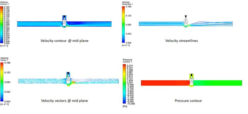
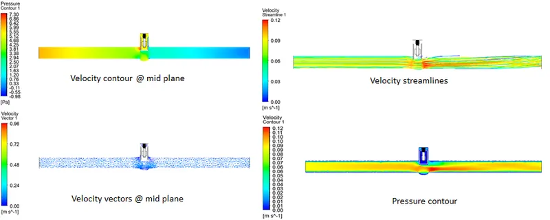
Velocity contour at midsection in ZY plane
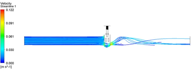
Velocity streamline
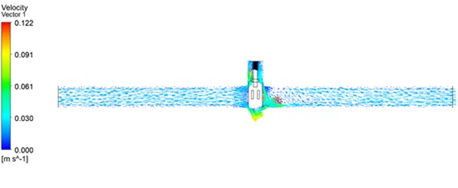
Velocity Vector
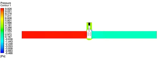
Pressure contour
Case 2: Gate valve lifted by 20 mm
Geometry
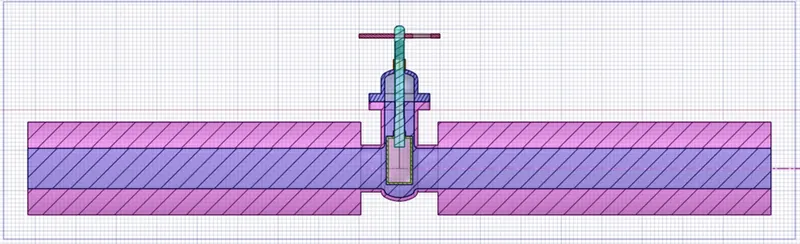
Meshing

Residual and Mass Flow rate Plot
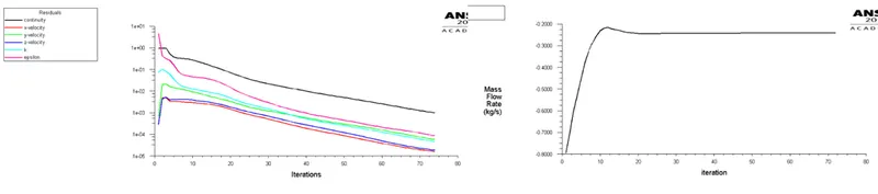
Results
Case 3: Gate valve lifted by 30 mm
Geometry
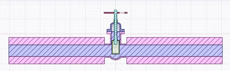
Meshing

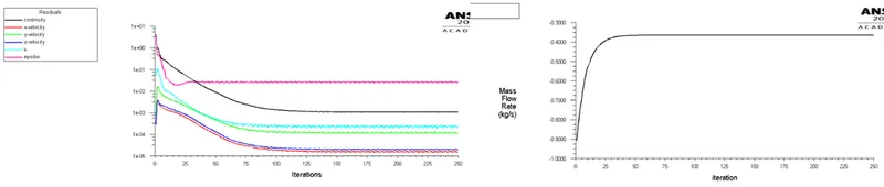
Residual and Mass Flow rate Plot
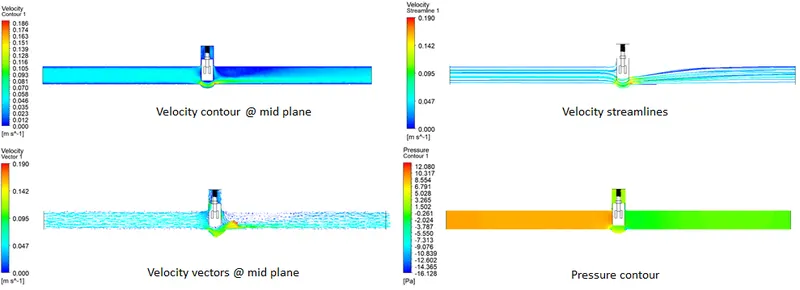
Results
Case 4: Gate valve lifted by 40 mm
Geometry
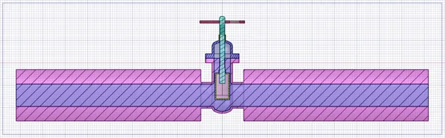
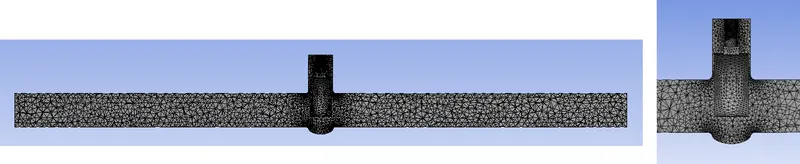
Meshing
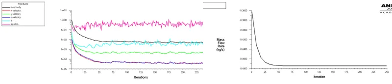
Residual and Mass Flow rate Plot
Results
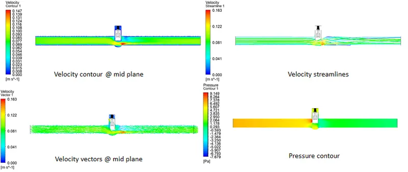
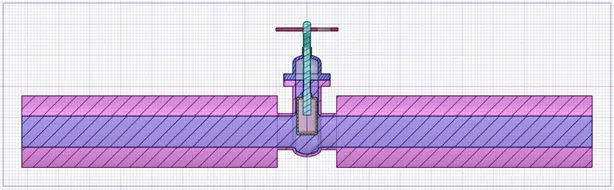
Case 5: Gate valve lifted by 50 mm
Geometry
Meshing

Residual and Mass Flow rate Plot
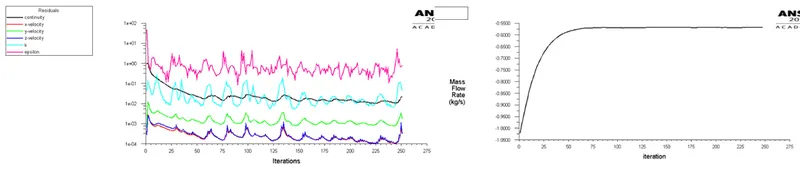
Results
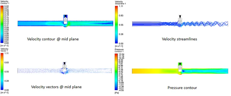
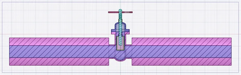
Case 6: Gate valve lifted by 60 mm
Geometry
Meshing

Residual and Mass Flow rate Plot
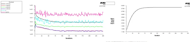
Results
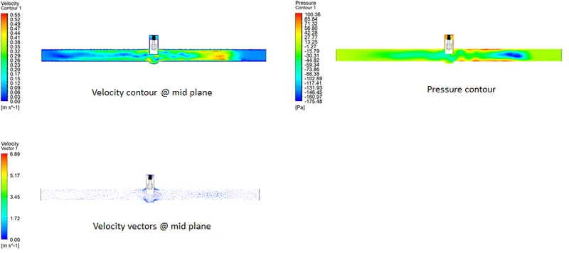
Case 7: Gate valve lifted by 70 mm
Geometry
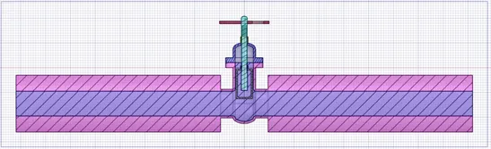
Meshing

Residual and Mass Flow rate Plot
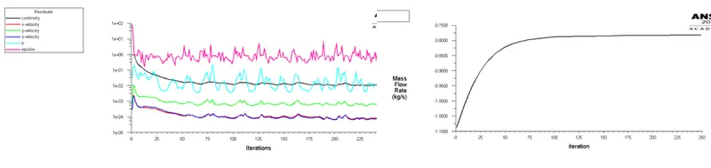
Results
Case 8: Gate valve is lifted by 80 mm
Geometry
Meshing

Residual and Mass Flow rate Plot
Results
Flow factor Kv =0.865* Cv
Flow coefficient Cv= Kv/0.865
Results Statistics
|
Case |
Mass flow rate (kg/s) |
Lift (mm) |
Flow coef. |
Flow factor |
|
Case 1 |
0.157 |
10 |
0.047 |
0.041 |
|
Case 2 |
0.241 |
20 |
0.076 |
0.065 |
|
Case 3 |
0.363 |
30 |
0.114 |
0.101 |
|
Case 4 |
0.472 |
40 |
0.149 |
0.129 |
|
Case 5 |
0.563 |
50 |
0.178 |
0.154 |
|
Case 6 |
0.643 |
60 |
0.203 |
0.176 |
|
Case 7 |
0.722 |
70 |
0.228 |
0.197 |
|
Case 8 |
0.785 |
80 |
0.249 |
0.215 |
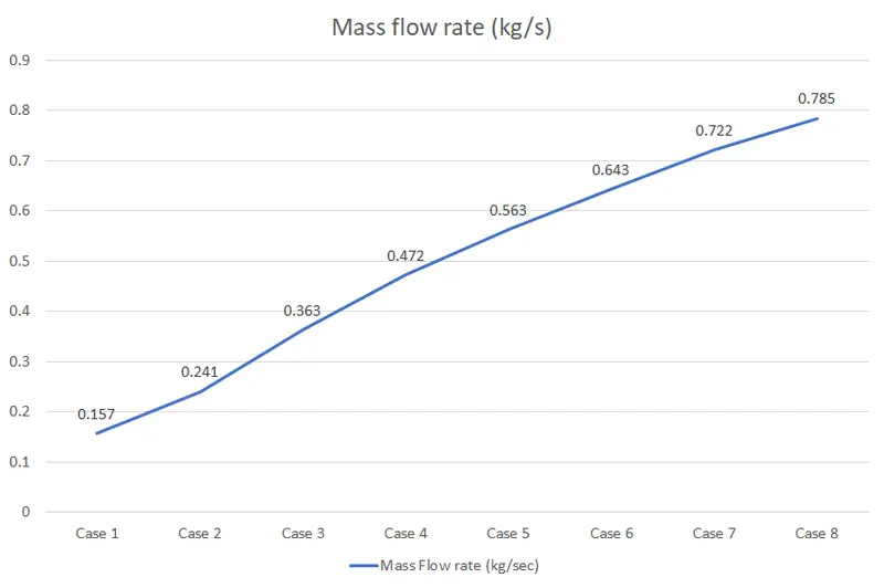
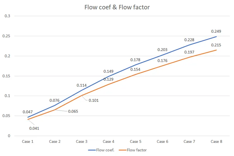
From the above Tabular Data and Graphs, we can observe that
- As the opening of the Gate Valve or Lift of the Gate Disc increases, the Mass Flow Rate increases.
- With Increases in Mass Flow Rate, there is an increment in Flow Coefficient.
- Also, Increases in Flow Factor are observed at each Design Point from 10 to 80 mm Lift.
- So, the Graph of Mass Flow Rate, Flow Coefficient, and Flow Factor goes linearly with Gate Disc Opening.
Mass flow rate graph for various cases
Flow factor and flow coefficient graph
Conclusion:
- Mass flow rate gradually increases as the lift of gate disc is increased.
- The variation of flow coefficient and flow factor with the opening of the valve is studied by using parametric.
- Parametric study is time reducing option when studying the effects of changes of certain parameters on a system.
- Flow coefficient plays important role in the selection of valve and sizing of a valve, so calculating it is necessary.
- flow coefficient also helps in computing the efficiency of the system and the effect of pressure on the system.