Week 9 - Parametric study on Gate valve.
Parametric study on Gate valve.
Aim: To perform a parametric study on the gate valve simulation by setting the opening from 10% to 80%
Objective:
Obtain the mass flow rates at the outlet for each design point.
Calculate the flow coefficient and flow factor for each opening and plot the graph.
Discuss the results of the mass flow rate and flow coefficient.
Introduction
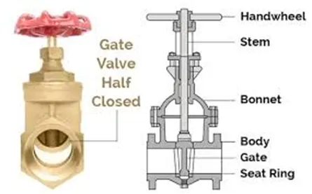
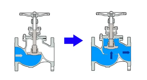
A control valve is a mechanical device that controls or modifies the flow of fluids such as gas, oil, water, and steam. It is an example of a final control element and a critical component of a control loop. The control valve is by far the most common final control device used in industry today. Electricity, pneumatics, or hydraulics can all be used to power a control valve. A linear motion valve's stem and valve movement is up and down. A gate valve is a type of sliding control valve.
https://www.youtube.com/watch?v=lD5Xn44Kbuo&t=31s
The following construction or Parts of Gate Valve
- Body
- Bonnet
- Disc
- Seat
- Stem and
- Manual actuators
Types of Gate valve:
- According to the types of disc
- Types of body bonnet joint and
- Types of stem movement
According to the types of disc
- Solid Wedge Valve
This is one of the oldest and most common valves. It can be installed in any position and also suitable for any fluid. It can also be used in a turbulent flow.
- Flexible Wedge Valve and
This type of disc is made in such a way it becomes flexible, by making cuts in the Periphery of the disc, it can resist thermal pressure. All the cuts are of different sizes, shapes, and depths.
- Split Wedge Valve
It consists of two discs, that are connected with each other parallelly to this is connected with each other through the mechanical mechanism.
Types of body bonnet joint:
Screwed bonnet: One of the simplest designs and used for inexpensive values.
Bolted bonnet: One of the popular designs, used in a large number of gate valves. It requires a gasket to seal the joint.
Welded bonnet: In this disassembly is not required. Light in weight than bolted bonnet counterparts.
Pressure seal bonnet: Extensively used for high pressure and high-temperature application. Higher body cavity more will be the force.
Types of stem movement:
Rising stem or OS and Y type (outside stem and screw type): There is an upward and downward movement of a stem for the movement of the valve.
Non-rising stem: There is no upward movement of the stem.
Material used for Gate Valve:
- Gray Cast Iron (FC200)
- Nodular Graphite Cast Iron (FCD450-10) and Ductile Iron Castings (FCD-S)
- Carbon Steel Castings for High Temperature/ Pressure Service (SCPH2)
- Stainless Steel Castings (SCS13A, SCS14A) and
- Bronze (CAC401, CAC406) and Brass (C3771
Ansys Fluent
Ansys Fluent is a general-purpose computational fluid dynamics (CFD) software used to model fluid flow, heat and mass transfer, chemical reactions, and more. Fluent offers a modern, user-friendly interface that streamlines the CFD process from pre- to post-processing within a single window workflow.
Geometry
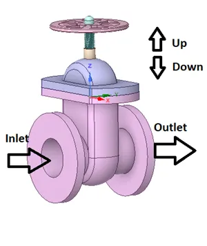
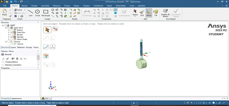
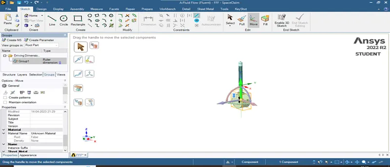
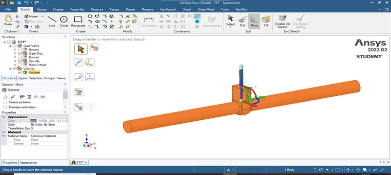
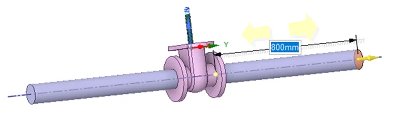
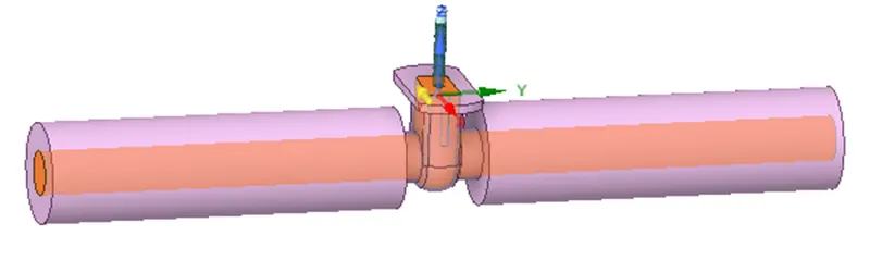
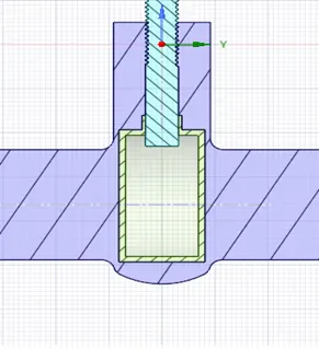
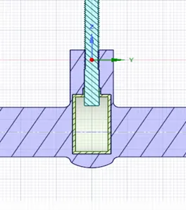
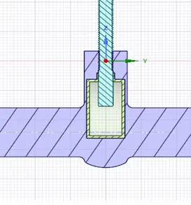
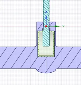
Open the fluid flow option in Ansys fluent. Import the gate valve geometry to the space-claim by opening the geometry tab. Conceal the gate valve's body and bonnet. Move the gate up for 10mm using the move tab and then select the parameter option. Under the prepare tab, enable only the bottom, gate disc, and spindle and pick the edges to extract the volume. Pull the inlet and outlet for 800mm using the pull tool.
 |
 |
 |
All other parts should be suppress for physics for analysis. In order to solve for 10% to 80% I choose 5 different cases like 10mm, 20mm, 40mm, 60mm and 80mm respectively.
In order to do the next parametric study, we need to follow these steps.
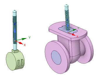
Uncheck the volume control. And, with only the gate disc and spindle enabled, move the gate disc up for 20mm. Now, check the box for volume and update volume in body context. Choose the bottom inlet once more and pull the inlet to 800mm and the outlet to the same size. We need update the volume in the body context again to expand the volume according to the bottom section. We can now observe how much of the gate disc is open by utilizing section mode.
Meshing
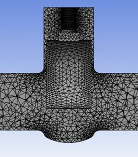
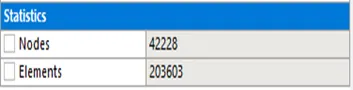
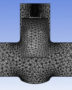
Initially the model is meshed on default mode and can be altered for finer mesh.
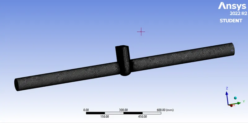
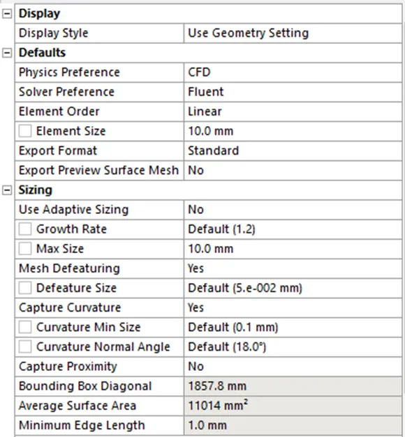
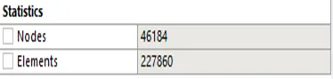
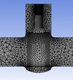
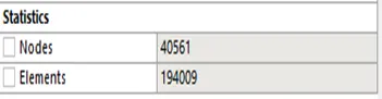
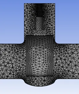
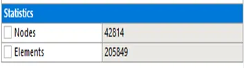
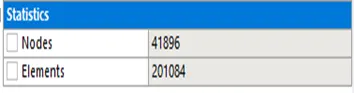
Finer mesh of 10mm mesh is generated on a body. Using the named selection create inlet and outlet faces on left and right side of the body.
Setup
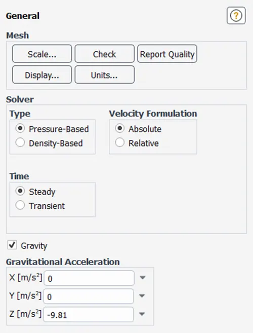
Ansys fluent is setup on the following changing setup. Gravity is enabled.
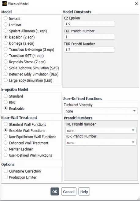
Viscous model is set as k-epsilon Realizable Scalable wall treatment.
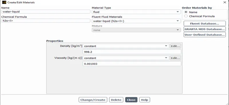
Create material from fluent database, water liquid material is added
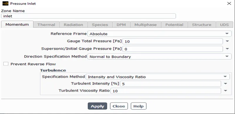
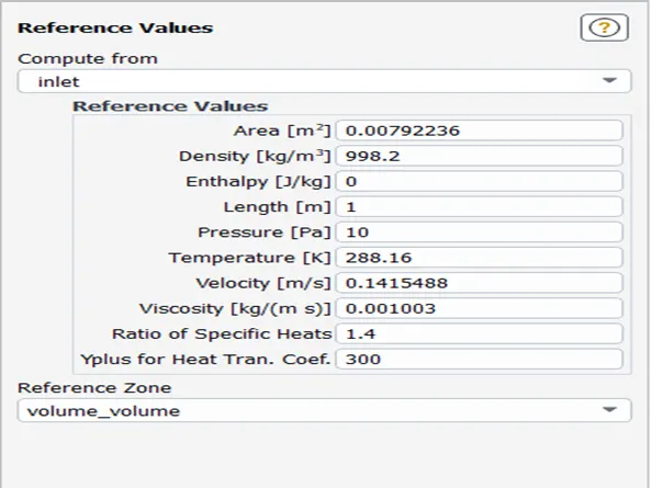
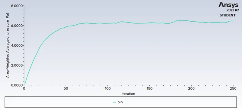
In boundary condition inlet should be changed to pressure inlet and 10pa is set as gauge total pressure.

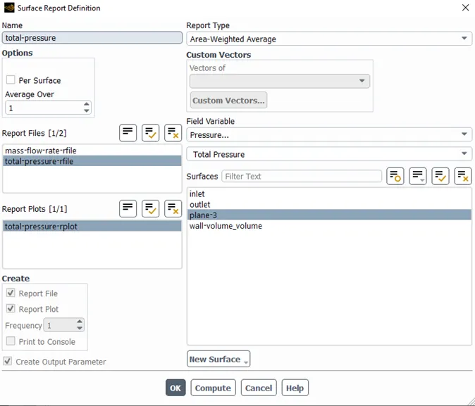
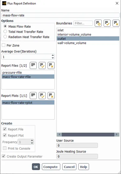
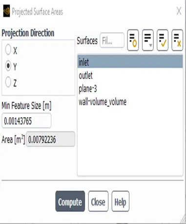
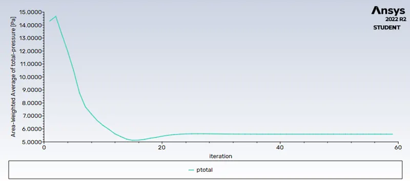
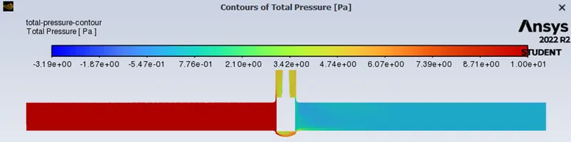
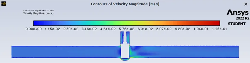
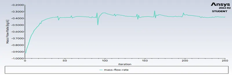
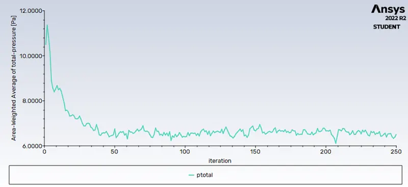
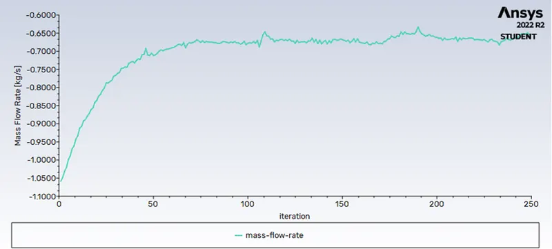
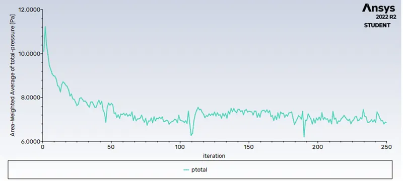
Creating a plane on YZ plane. Surface report for total pressure is set on the created plane. Flux report for mass flow rate is defined for outlet.
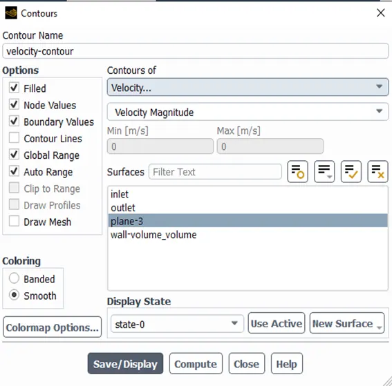
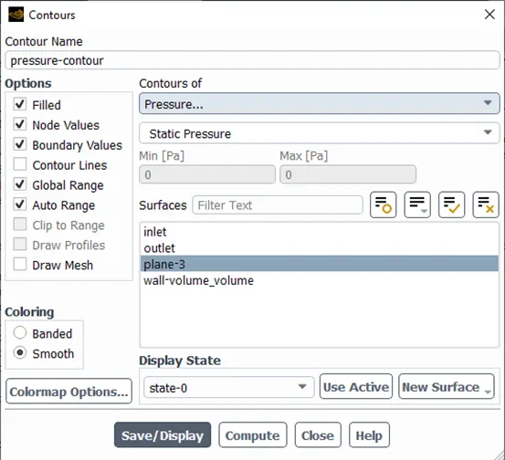
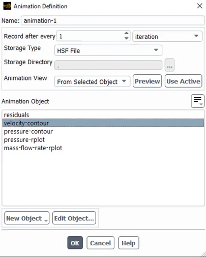
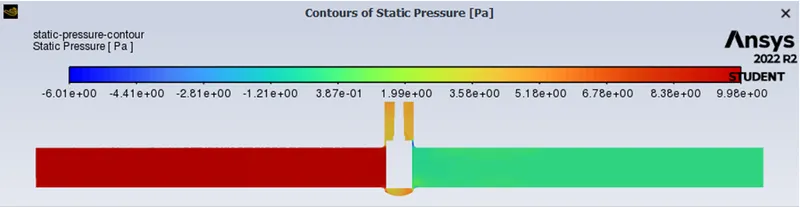
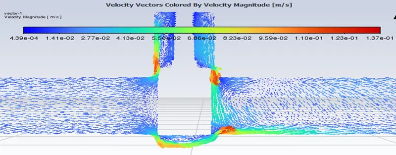
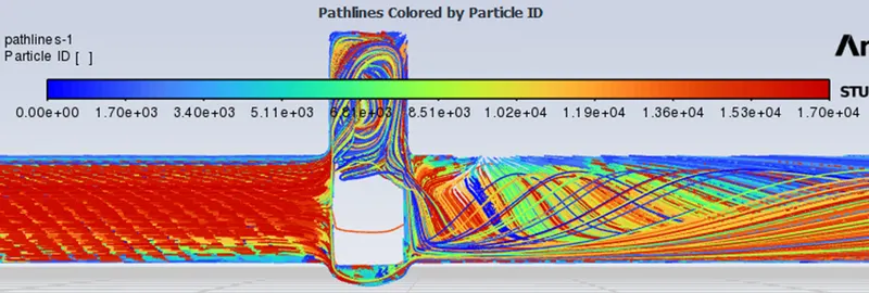
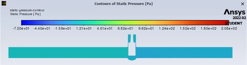
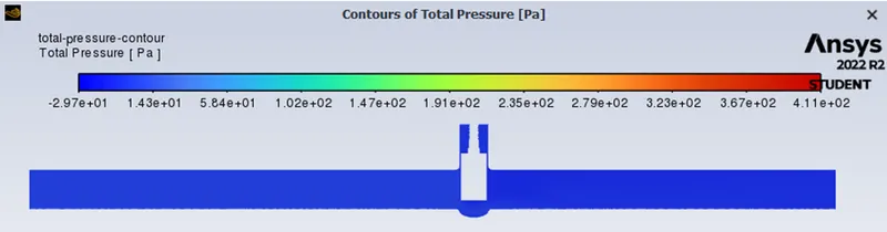
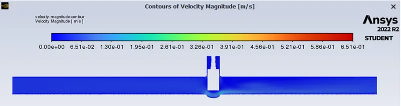
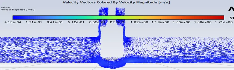
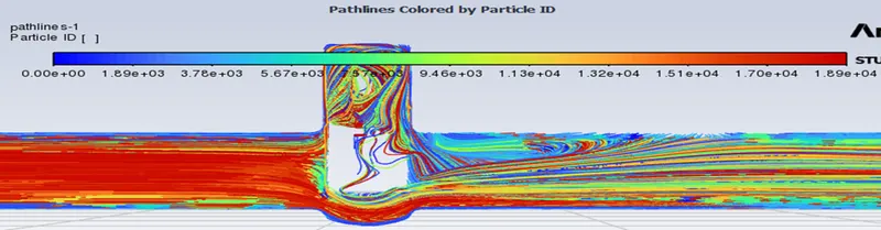
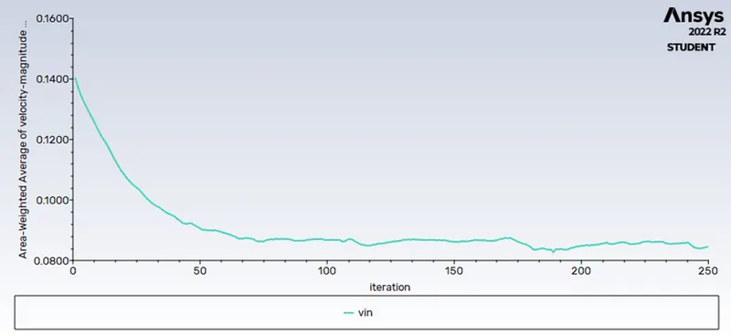
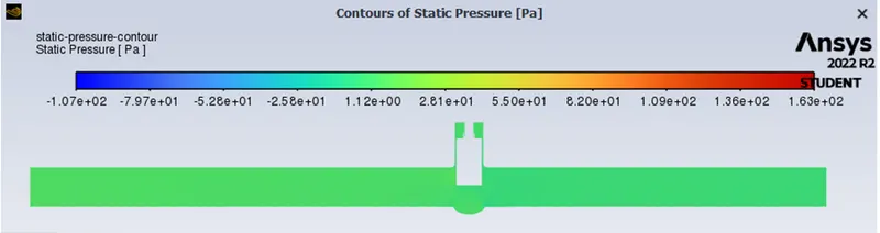
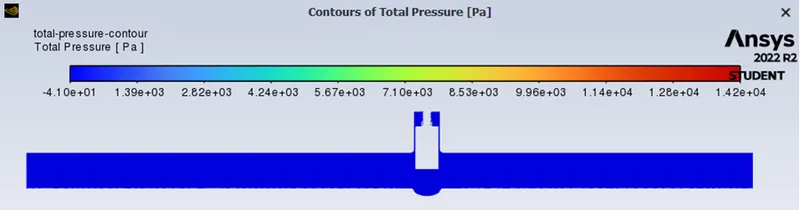
Velocity and pressure contours on the created plane. And velocity animation is created for the analysis
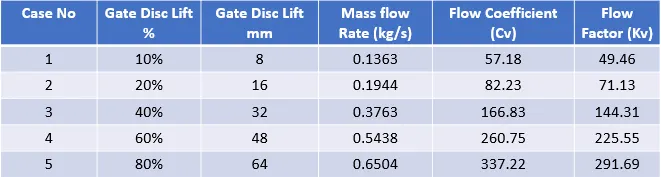
Case1-8mm, Case2-16mm, Case3-32mm, Case4-48mm, Case5-64mm
Result
Case1-8mm open
 |
 |
|
 |
 |
 |
 |
 |
|
 |
 |
 |
 |
 |
|
Flow Coefficient (Cv)& Flow Factor (Kv)
Flow loses energy when it passes through a valve or other restricting device. The flow coefficient is a design factor that connects the flow rate (Q) to the head drop (h) or pressure drop (P) over the valve.
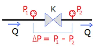
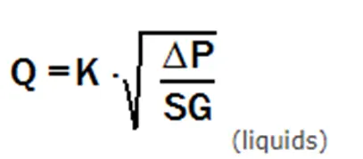
Q: Flow rate
ΔP: Pressure Drop
Sg: Specific gravity (1 for water)
K: Flow coefficient Kv or Cv Kv = 0.865 * Cv Cv = 1,156 * Kv
The flow coefficient in metric units is denoted by Kv. It is defined as the flow rate of water in cubic metres per hour [m3/h] at 16 degrees Celsius and a pressure drop across the valve of 1 bar.
The flow coefficient in imperial units is denoted by Cv. It is defined as the flow rate of water in US gallons per minute [gpm] at 60 degrees Fahrenheit and a pressure drop across the valve of 1 psi.
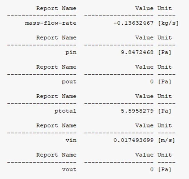
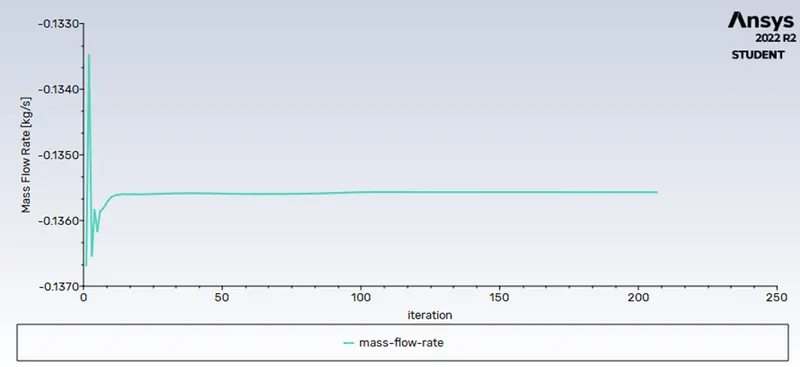
Q = 0.13632 kg/sec Convert it into Galloons/min; 1 kg/sec = 15.85 gal/min.
Q = 2.160672 gal/min.
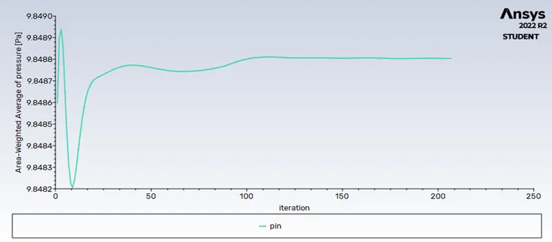
Pressure at Inlet = 9.847 Pascal, Pressure at Outlet = 0 Pascal. Then Pressure Drop = Pin-Pout => 9.847 Pascal convert it into Psi 1 Pascal = 0.000145 psi.
Pressure Drop(∆P) = 0.0014278 psi.
Specific Gravity = 1 for water.
Cv = 57.181
Kv = 0.865*Cv
Kv = 49.46
Case2-16mm open
 |
 |
|
 |
 |
 |
 |
 |
|
 |
 |
 |
 |
 |
|
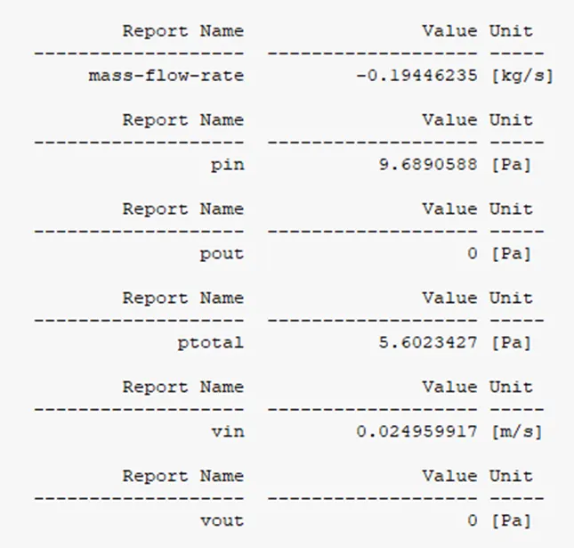
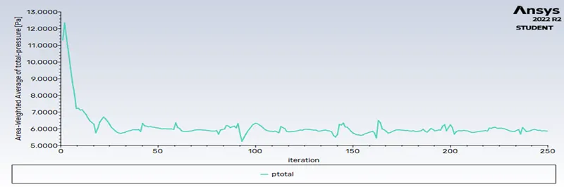
Q = 0.1944 kg/sec Convert it into Galloons/min; 1 kg/sec = 15.85 gal/min.
Q = 3.08124 gal/min.
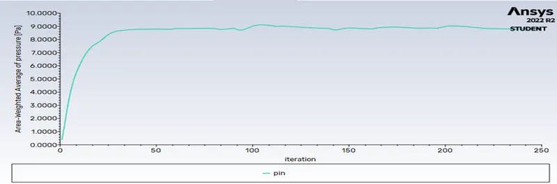
Pressure at Inlet = 9.6890 Pascal, Pressure at Outlet = 0 Pascal. Then Pressure Drop = Pin-Pout => 8.8181 Pascal convert it into Psi 1 Pascal = 0.0001456 psi.
Pressure Drop(∆P) = 0.001404 psi.
Specific Gravity = 1 for water.
Cv = 82.232
Kv = 0.865*Cv
Kv = 71.13
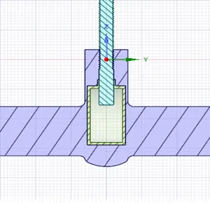
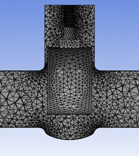
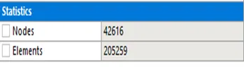
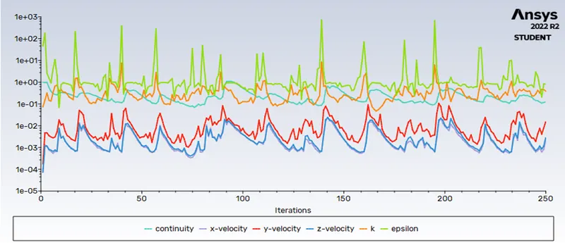
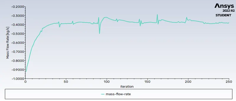
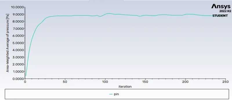
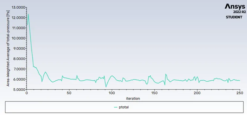
Case3-32mm open
|
|
|
|
 |
 |
 |
 |
 |
|
|
|
|
 |
 |
|
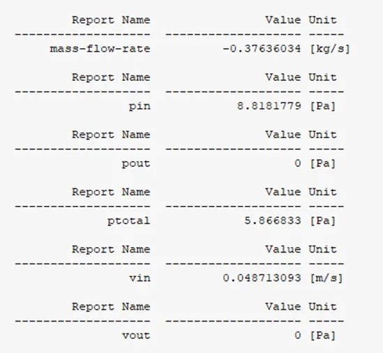
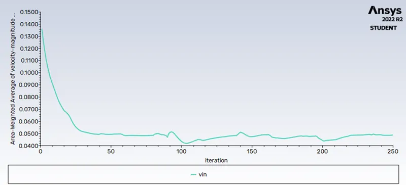
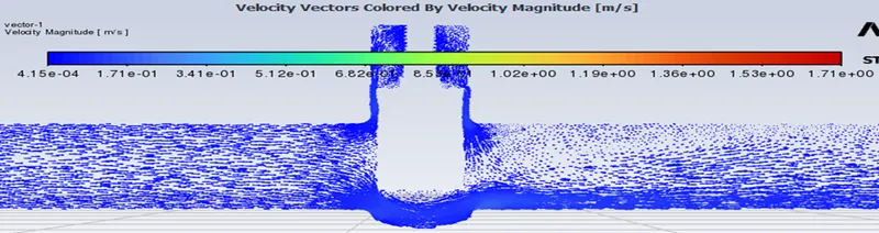
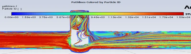
Q = 0.3763 kg/sec Convert it into Galloons/min; 1 kg/sec = 15.85 gal/min.
Q = 5.96435 gal/min.
Pressure at Inlet = 8.8181 Pascal, Pressure at Outlet = 0 Pascal. Then Pressure Drop = Pin-Pout => 8.8181 Pascal convert it into Psi 1 Pascal = 0.0001456 psi.
Pressure Drop(∆P) = 0.001278 psi.
Specific Gravity = 1 for water.
Cv = 166.83
Kv = 0.865*Cv
Kv = 144.31
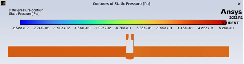
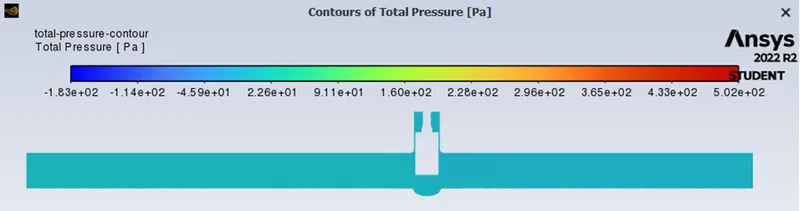
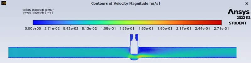
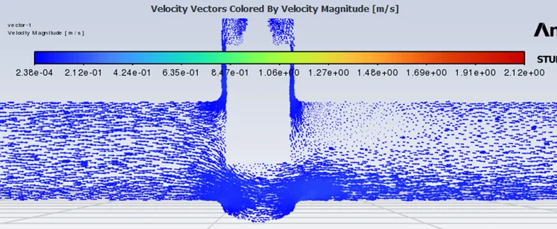
Case4-48mm open
|
|
|
|
 |
 |
 |
 |
 |
|
 |
 |
 |
 |
 |
|
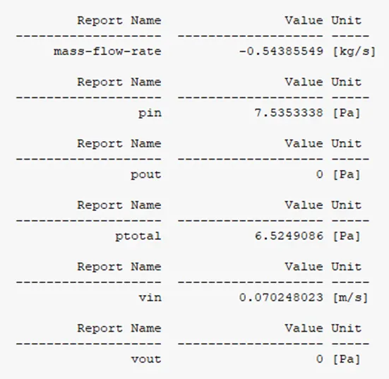
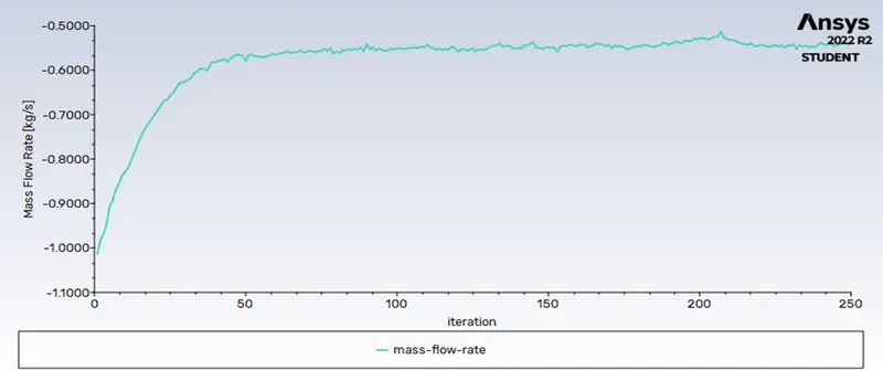
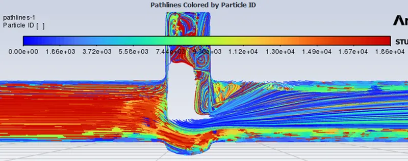
Q = 0.5438 kg/sec Convert it into Galloons/min; 1 kg/sec = 15.85 gal/min.
Q = 8.61923 gal/min.
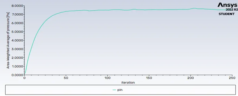
Pressure at Inlet = 7.5353 Pascal, Pressure at Outlet = 0 Pascal. Then Pressure Drop = Pin-Pout => 8.8181 Pascal convert it into Psi 1 Pascal = 0.0001456 psi.
Pressure Drop(∆P) = 0.0010926 psi.
Specific Gravity = 1 for water.
Cv = 260.75
Kv = 0.865*Cv
Kv = 225.55
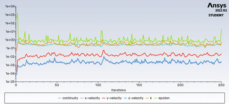
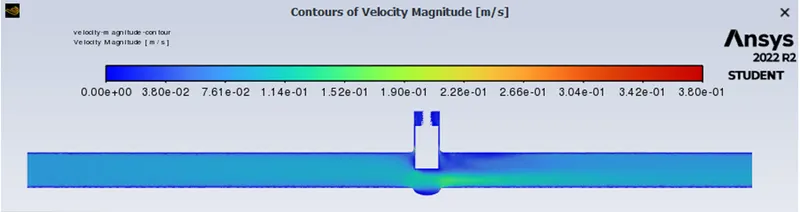
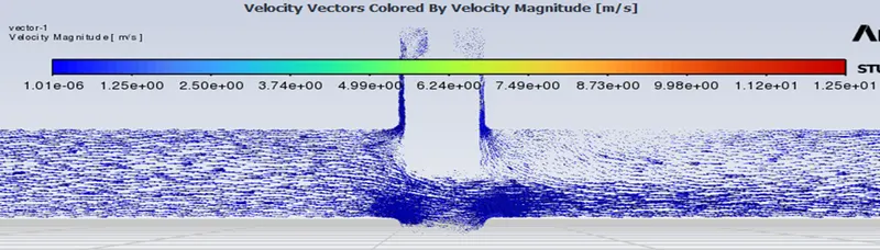
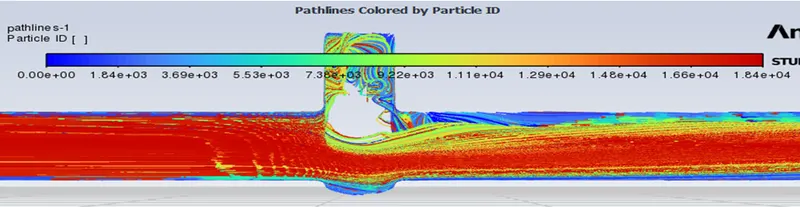
Case5-64mm open
|
|
|
|
 |
 |
 |
 |
 |
|
 |
 |
 |
 |
 |
|
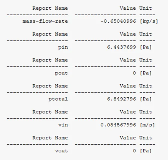
Q = 0.6504 kg/sec Convert it into Galloons/min; 1 kg/sec = 15.85 gal/min.
Q = 10.30884 gal/min.
Pressure at Inlet = 6.4437 Pascal, Pressure at Outlet = 0 Pascal. Then Pressure Drop = Pin-Pout => 8.8181 Pascal convert it into Psi 1 Pascal = 0.0001456 psi.
Pressure Drop(∆P) = 0.0009345 psi.
Specific Gravity = 1 for water.
Cv = 337.225
Kv = 0.865*Cv
Kv = 291.69
The metric equivalent flow factor (Kv) is calculated using metric units:
where,
Kv is the flow factor (expressed in m3/hr.).
Q is the mass flow rate (expressed in cubic metres per hour m3/hr.),
SG is the specific gravity of the fluid (for water = 1),
∆P is the differential pressure across the device (expressed in bar).
Conclusion:
- Ansys Fluent was utilized to perform a parametric analysis on the gate valve simulation by changing the opening at various lifts.
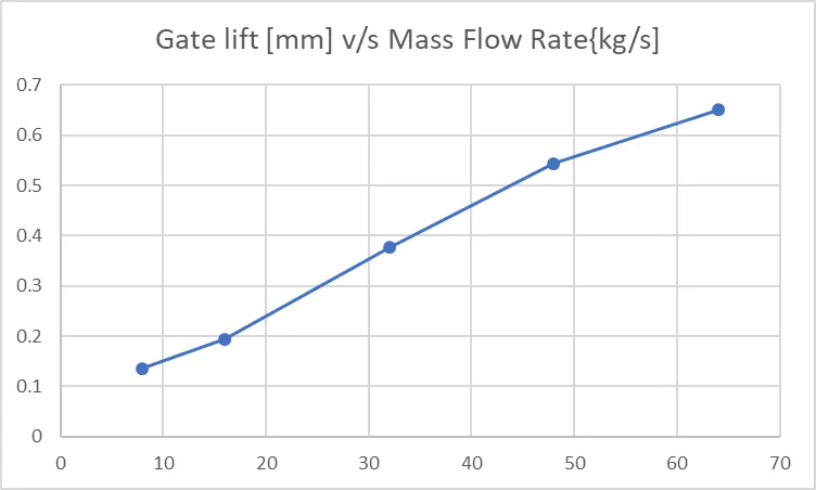
- The mass flow rate at the outflow has been determined for each design point. As the valve is opened, the mass flow rate increases.
- The mass is largest when the valve is fully opened. The pressure at the inlet is greatest when the valve is closed.
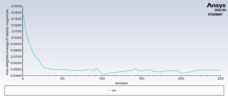
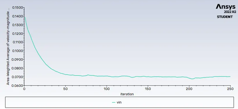
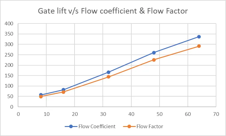
- Velocity rises with valve opening and plateaus at a certain percentage of valve opening. As the valve opening increases, so does the flow factor (Kv).
- As the valve opening grows, so does the flow coefficient (Cv).