Week 9 - Parametric study on Gate valve.
Aim:
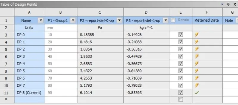
To perform a parametric study on gate valve by setting the opening from 10% to 80%.
Objectives:
- To obtain the mass flow rates at the outlet for each design point.
- To calculate the flow coefficient and flow factor for each opening and plot the graph.
- Discuss the results of the mass flow rate and flow coefficient.
Introduction:
Gate valve:
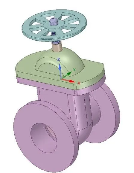
A gate valve is also known as a sluice valve that opens by lifting a barrier (gate disc) through which the fluid is allowed to flow. Gate valves require very little space along the pipe axis and hardly restrict the flow of fluid when the gate is fully opened. The gate faces can be parallel but are most commonly wedge-shaped (in order to be able to apply pressure on the sealing surface).
Uses of gate valve:
- Gate valves are used to shut off the flow of liquids rather than for flow regulation. When fully open, the typical gate valve has no obstruction in the flow path, resulting in very low flow resistance. The size of the open flow path generally varies in a nonlinear manner as the gate is moved. This means that the flow rate does not change evenly with stem travel. Depending on the construction, a partially open gate can vibrate from the fluid flow.
- Gate valves are mostly used with larger pipe diameters (from 2" to the largest pipelines) since they are less complex to construct than other types of valves in large sizes.
- Gate valves without an extra sealing ring on the gate or the seat are used in applications where minor leaking of the valve is not an issue, such as heating circuits or sewer pipes.
Geometry:
Original geometry
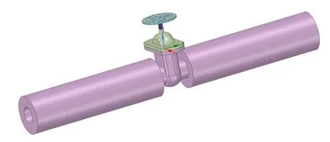
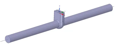
Modified geometry:
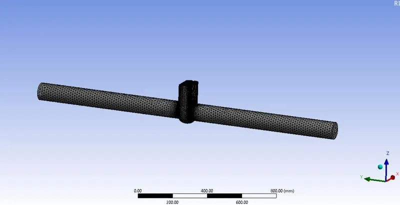
Mesh:
Flow Coefficient:
The flow coefficient of a device is a relative measure of its efficiency at allowing fluid flow. It describes the relationship between the pressure drop across an orifice valve or other assembly and the corresponding flow rate.
Mathematically the flow coefficient Cv (or flow-capacity rating of valve) can be expressed as:
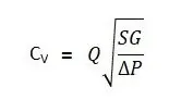
Where:
- Q is the rate of flow (expressed in US gallons per minute).
- SG is the specific gravity of the fluid (for water = 1).
- ΔP is the pressure drop across the valve (expressed in psi).
In more practical terms, the flow coefficient Cv is the volume (in US gallons) of water at 60 °F that will flow per minute through a valve with a pressure drop of 1 psi across the valve.
The use of the flow coefficient offers a standard method of comparing valve capacities and sizing valves for specific applications that is widely accepted by industry. The general definition of the flow coefficient can be expanded into equations modeling the flow of liquids, gases and steam using the discharge coefficient.
Flow Factor:
The metric equivalent flow factor (Kv; commonly used in Europe and Asia) is calculated using metric units:
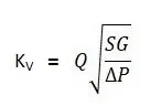
Where:
- Kv is the flow factor (expressed in). Q is the flow rate (expressed in cubic meters per hour.
- SG is the specific gravity of the fluid (for water = 1).
- ∆P is the differential pressure across the device (expressed in [bar]).
Kv can be calculated from Cv using the equation as given below:
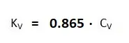
The kv factor of a valve indicates "The water flow in m3/h, at a pressure drop across the valve of 1 kgf /cm2 when the valve is completely open.
Case Setup Details:
Analysis type: Steady state
Solver: Pressure based solver
Gravity: -9.81 m/s2 in Z-Direction
water-liquid (h2o)
Viscous Model:
Model - K-Epsilon
K-Epsilon Model - Realizable
Near Wall Treatment - Scalable Wall Functions
InletType: Pressure-Inlet
Gauge Total Pressure - 10 Pa
OutletType - Pressure-outlet
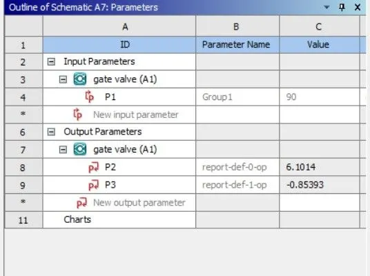
Parameters:
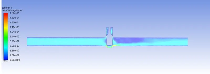
Case 1:
10mm lift
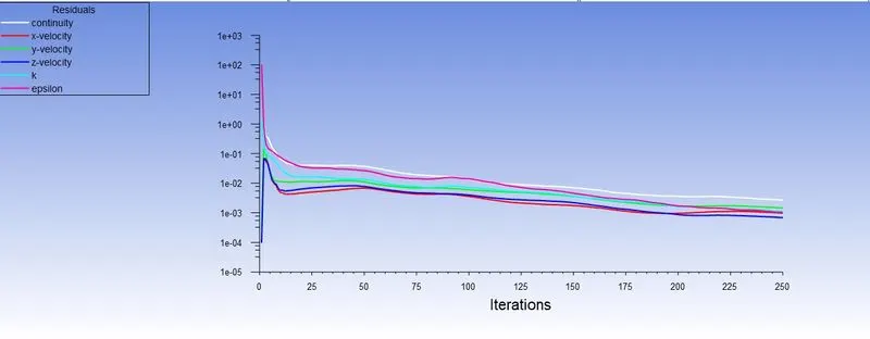
Scaled Residuals
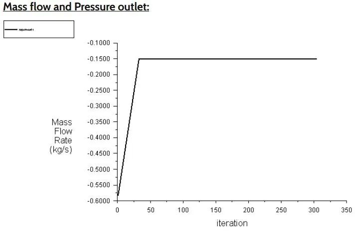
Mass flow
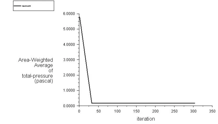
Pressure
Velocity contour:
Case 2:
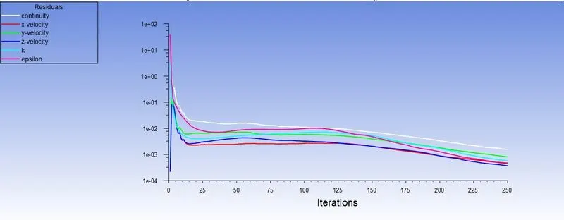
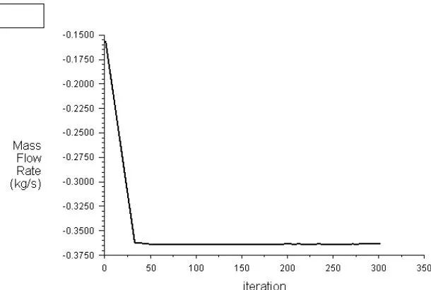
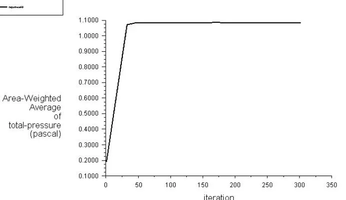
20mm lift
Scaled Residuals
Mass flow
Pressure
Velocity contour:
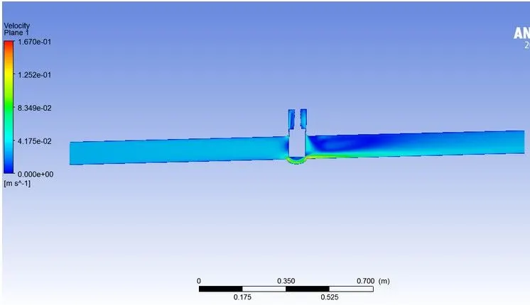
Case 3
30mm lift
Scaled Residuals
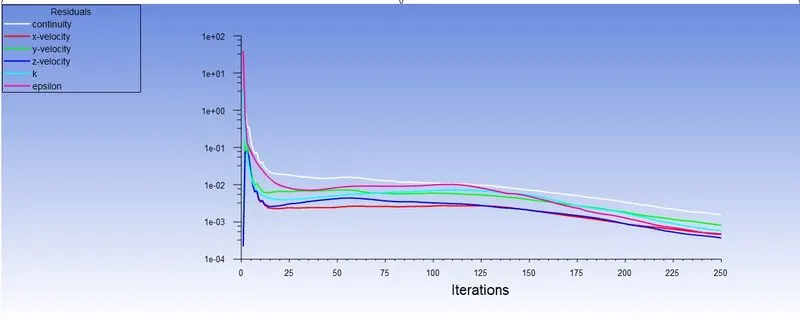
Mass flow
Pressure
Velocity contour:
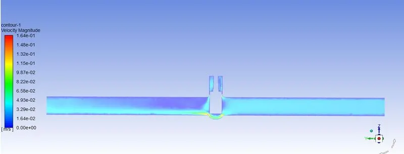
Case 4
40mm lift
Scaled Residuals
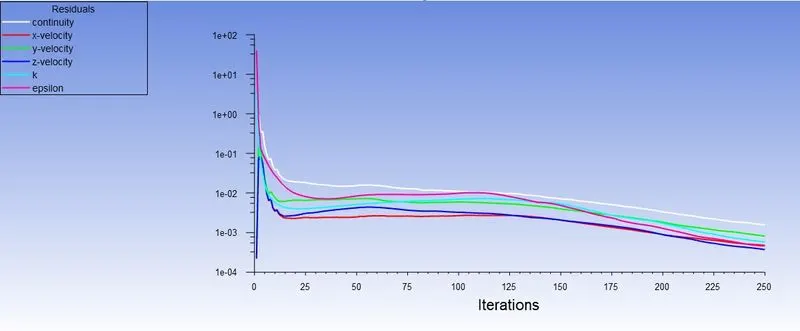
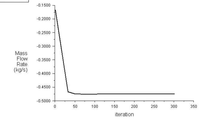
Mass flow
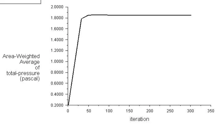
Pressure
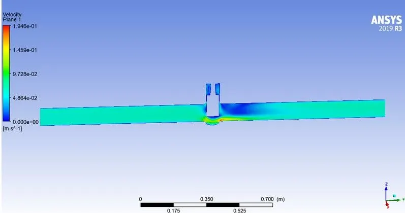
Velocity contour:
Case 5
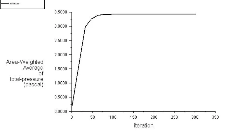
60mm lift
Scaled Residuals
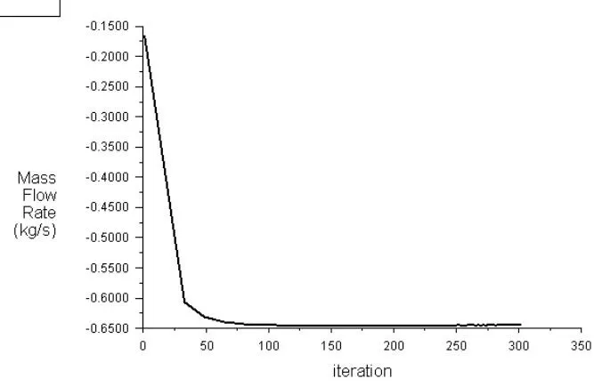
Mass flow
Pressure
Velocity contour:

Case 6
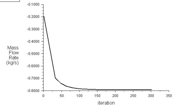
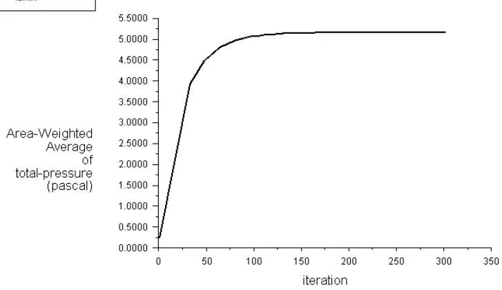
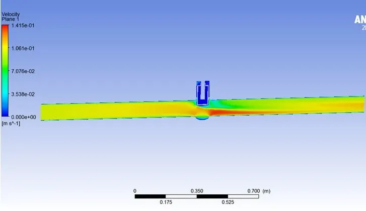
80mm lift
Scaled Residuals
Mass flow
Pressure
Velocity contour:
|
Lift mm |
Pin |
Pout |
Pr drop |
Q m3/hr |
Kv |
Cv |
|
10 |
10 |
0.14928 |
9.85072 |
0.661 |
0.210604 |
0.243459 |
|
20 |
10 |
0.24069 |
9.75931 |
1.737 |
0.55602 |
0.642759 |
|
30 |
10 |
0.36311 |
9.63689 |
3.907 |
1.258563 |
1.454899 |
|
40 |
10 |
0.47429 |
9.52571 |
6.671 |
2.161435 |
2.498619 |
|
60 |
10 |
0.64389 |
9.35611 |
12.356 |
4.039524 |
5.824615 |
|
80 |
10 |
0.79033 |
9.20967 |
18.647 |
6.144505 |
7.103048 |
Conclusion:
- The negative sign in the mass flow rate term comes due to mass leaving at the outlet.
- Parametric study helps a lot to reduce the solving time in studying the effect of change of parameters on the system.
- As flow rate is increased, flow factor (Kv) increases as a result of which flow co-efficient (Cv) also increased.