Week 9 - Parametric study on Gate valve.
AIM:- Parametric Study for a Gate Valve
Objectives:-
- To perform the parametric study on the gate valve by simulating the opening of gate valve ranging from 10mm to 80mm.
- To obtain the mass flow rate for each design point.
- Calculate the flow factor and flow coefficient for each design point.
Theory:
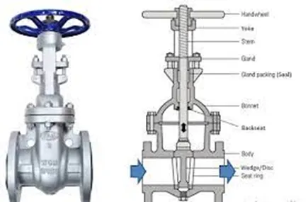
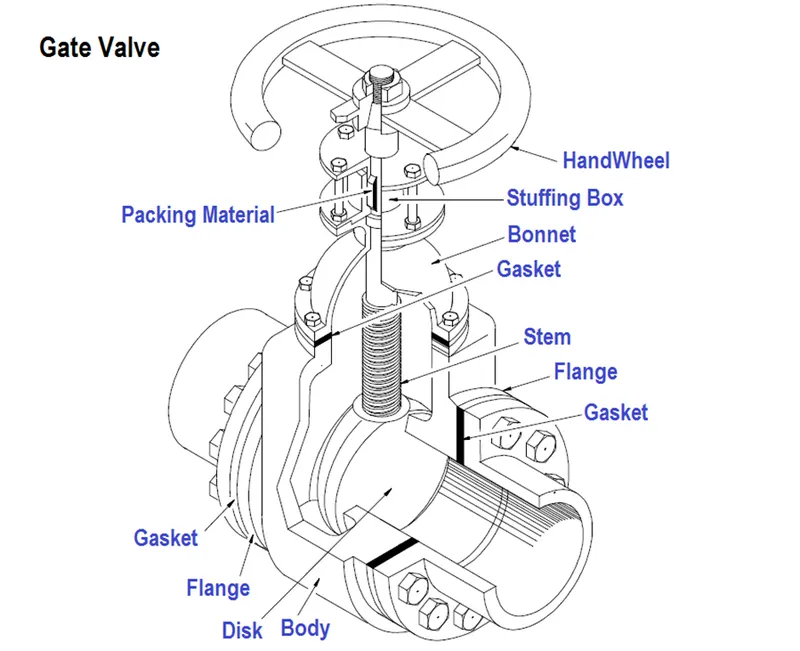
Gate valves work by inserting a rectangular gate or wedge into the path of a flowing fluid. They are operated by a threaded stem which connects the actuator (generally a hand wheel or motor) to the stem of the gate. If the valve has a rising stem its position can be seen just by looking at the position of the stem. A gate valve is used to control the fluid flow through lifting and descending the gate. A gate distinct feature is to provide an unobstructed passageway, which includes minimal pressure loss over the valve.
When the gate is fully opened there is no restriction to the flow hence the pressure drop is low comparatively. Generally, the gate valve are fully closed or fully open as partially opened valve may experience vibration which may lead to excessive wear. A gate valve's main component is body, seat, gate, stem, bonnet, and actuator. the primary mechanism is straight forward where the handwheel is rotated to move the gate up and down via threads. they require more than a 360-degree turn to fully open the valve.
Gate valves tend to be slightly cheaper than ball valves of the same size and quality. They are slower in actuation than quarter-turn valves and are for applications where valve operation is infrequent, such as isolating valves. Gate valves should be used either fully open or fully closed, not to regulate flow. Automated gate valves exist with either an electric or pneumatic actuator, but a manual gate valve is cost-effective since they have infrequent usage. Gate valves are widely used for all types of applications and are suitable for both above-ground and underground installation. They are suitable for most fluids including steam, water, oil, and gas, etc.
Modeling
The mode for the gate valve can be prepared in any CAD software and thus can be imported in Ansys Space Claim.
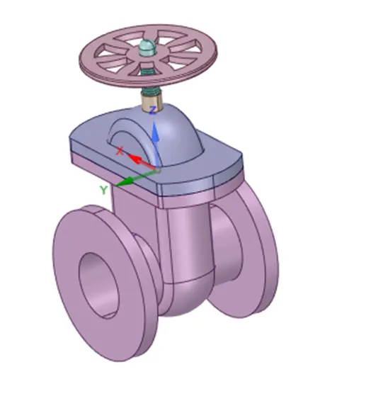
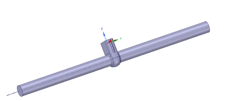
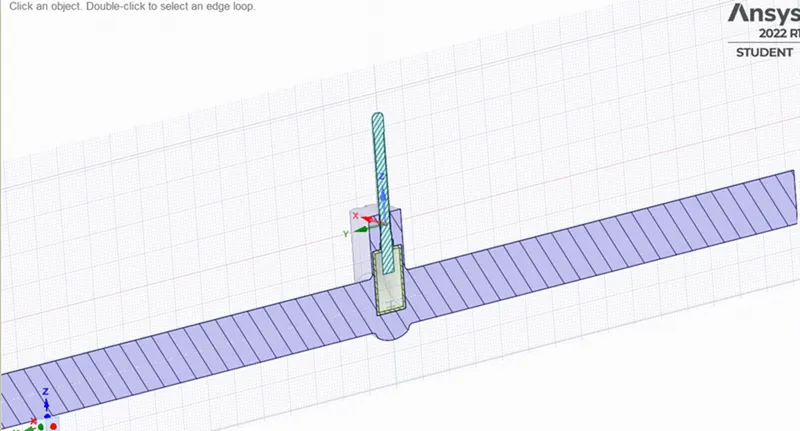
The model once imported is checked for any incoming errors such as extra edges and others. Once the errors are repaired the flanges on both the sides of the gate valve are pulled by 800mm to simulate the proper flow while defining the inlet and the outlet for the fluent. It can be seen below:
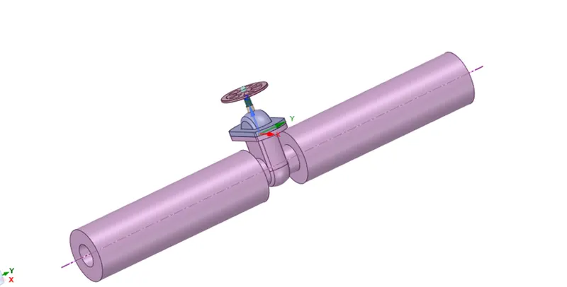
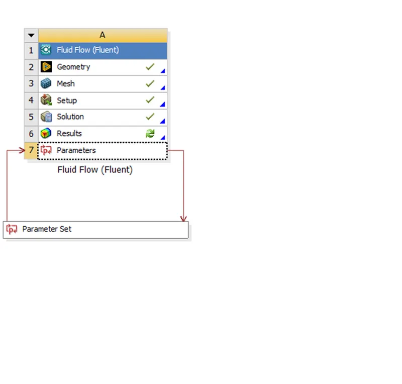
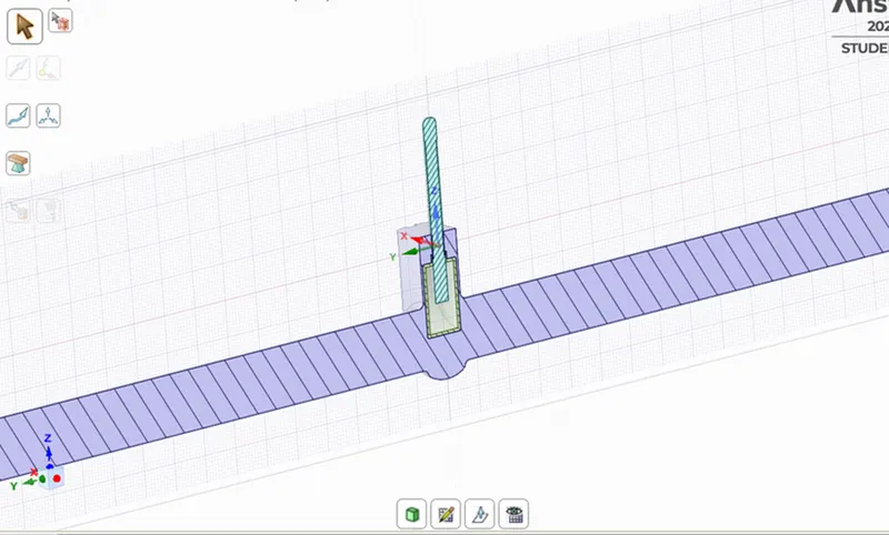
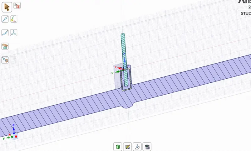
Further the gate disc is moved by 10mm towards the handwheel and the valve is then parameterised by cling the 'P' button and the group is then created. Volume is then extraced using the volume extract command and the volume is updated in context to update the valume as the parameter changes.
Meshing
The model is then imported into the mechanical module for the mesh generation where all the input parameters are kept as default and the mesh size is set as 6mm.
The number of nodes is 87339 and the number of elements is 414055. The mesh can be seen below;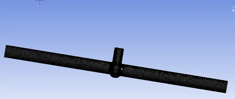
The element quality is further checked and it can be noted that all the elements are in the good element quality range:
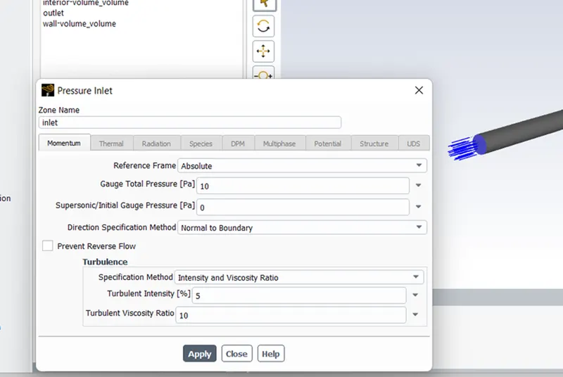
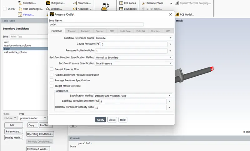
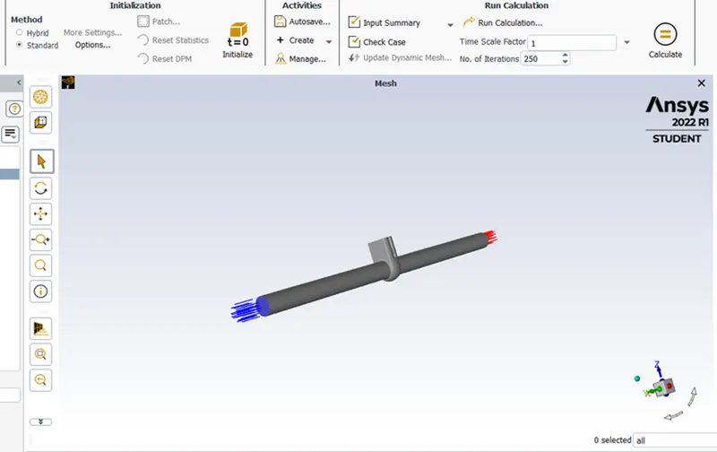
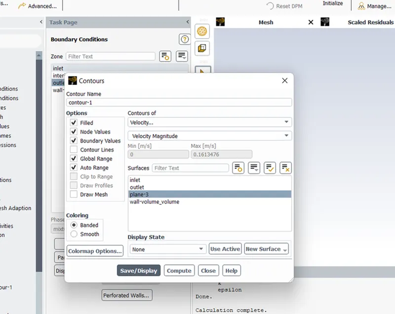
Setup:
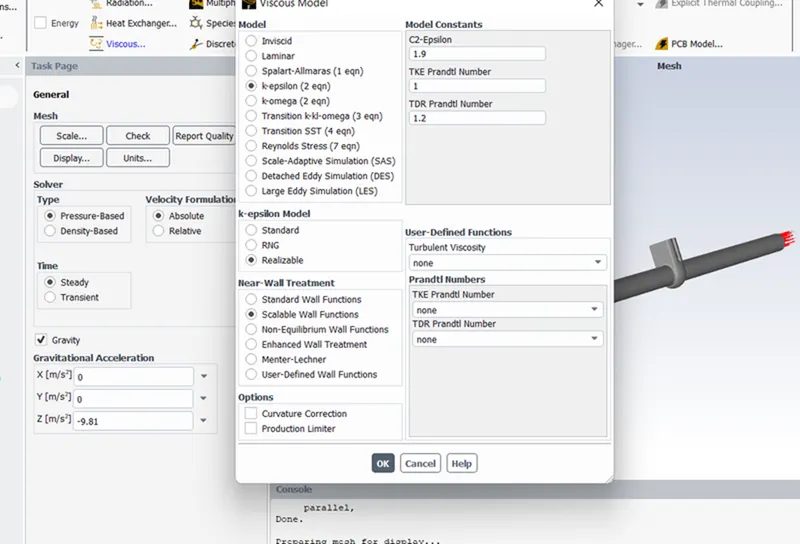
Preprocessing: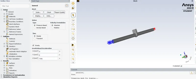
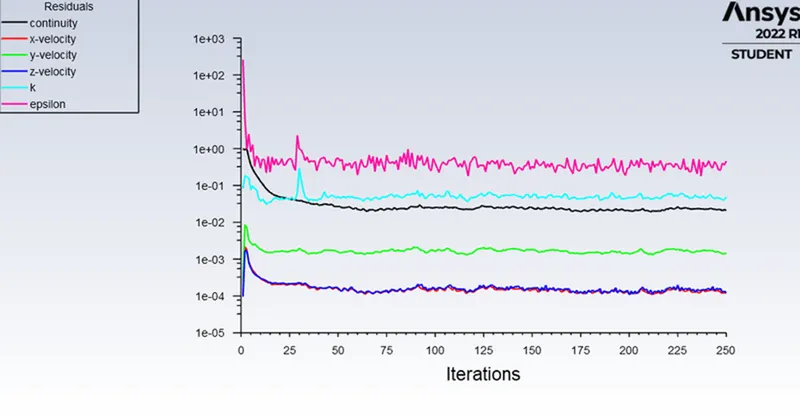
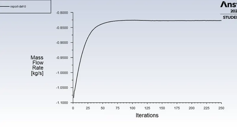
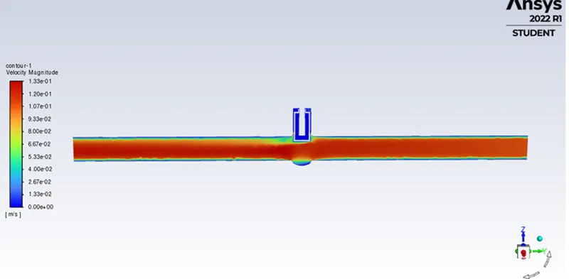
RESULT:
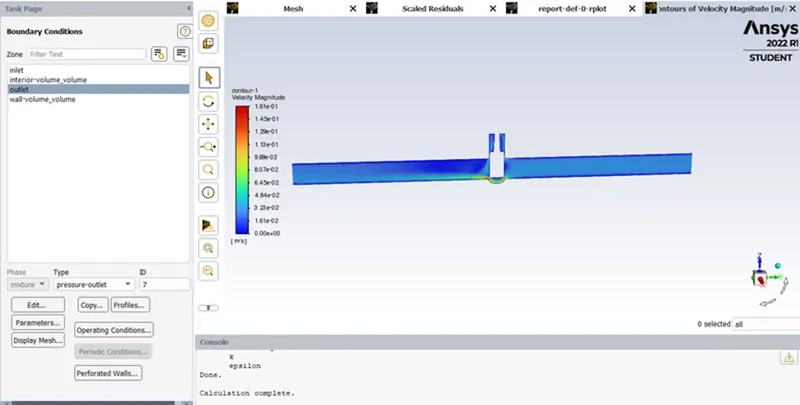
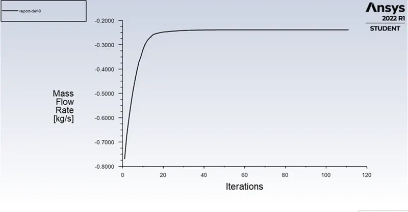
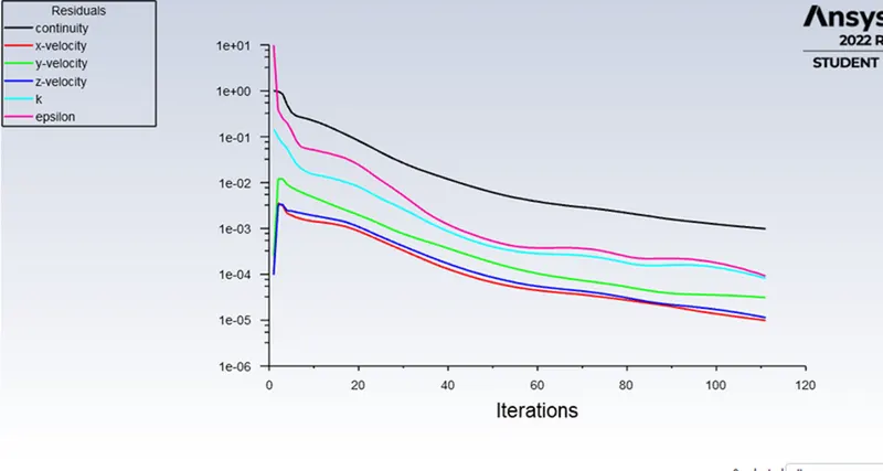
opened at 30%:
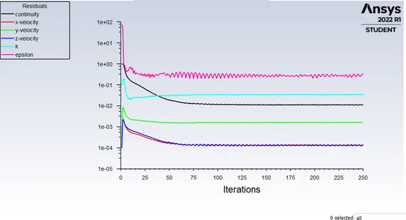
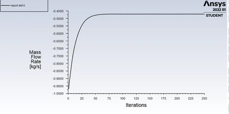
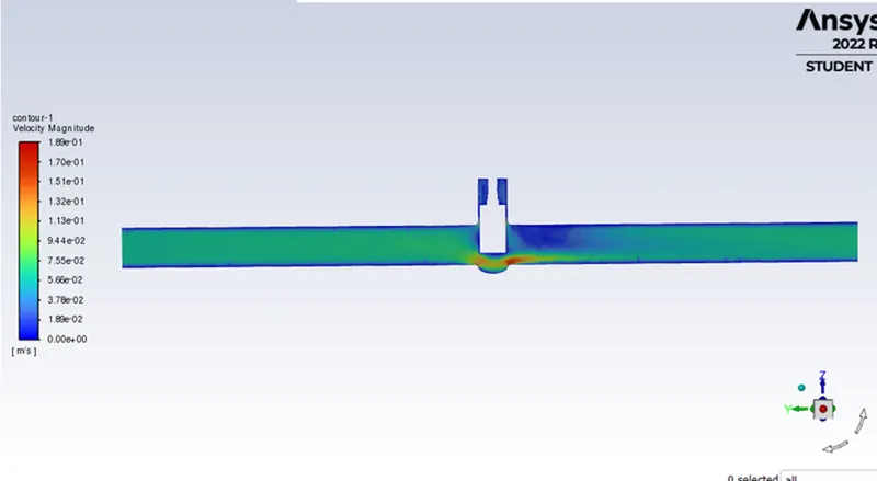
Opening at 50%:

opening at 80%:
Conclusion:
- Flow-coefficient and flow-factor increase with increasing opening percentage.
- Differential pressure across the gate valve decreases with increasing opening percentage. This is because there is less blockage to the flow.
- Mass-flow rate and velocity increase with increasing opening percentage. This is because there are more pathways for the water to flow.
- Gate valve should operate in a fully-opened or fully-closed position. A partially-opened valve induces vibration which can damage the gate valve.
- Also the gate valve should be closed gradually rather than suddenly, as it causes a water hammer effect which can again damage the gate valve.