Week 9 - Parametric study on Gate valve.
Aim: To perform a parametric study on the gate valve simulation.
Objectives:
The aim of this project is to carry out a parametric study on the gate valve by setting the opening from 10% to 80% with the objective to:
- Obtain the mass flow rates at the outlet for each design point
- Calculate the flow coefficient and flow factor for each opening and plot the graph
- Discuss the results of the mass flow rate and flow coefficient
INTRODUCTION
A gate valve, also known as a sluice valve, is a valve that opens by lifting a barrier (gate) out of the path of the fluid. Gate valves require very little space along the pipe axis and hardly restrict the flow of fluid when the gate is fully opened. The gate faces can be parallel but are most commonly wedge-shaped.
Gate valves are used to shut off the flow of liquids rather than for flow regulation. When fully open, the typical gate valve has no obstruction in the flow path, resulting in very low flow resistance. The size of the open flow path generally varies in a nonlinear manner as the gate is moved. This means that the flow rate does not change evenly with stem travel. Depending on the construction, a partially open gate can vibrate from the fluid flow.
Gate valves are mostly used with larger pipe diameters (from 2" to the largest pipelines) since they are less complex to construct than other types of valves in large sizes.
At high pressures, friction can become a problem. As the gate is pushed against its guiding rail by the pressure of the medium, it becomes harder to operate the valve. Large gate valves are sometimes fitted with a bypass controlled by a smaller valve to be able to reduce the pressure before operating the gate valve itself.
Gate valves without an extra sealing ring on the gate or the seat are used in applications where minor leaking of the valve is not an issue, such as heating circuits or sewer pipes.
In this project parametric study is performed at various valve position. mass flow rate is checked at various valve position.
Use
- Gate valves are used to shut off the flow of liquids rather than for flow regulation. When fully open, the typical gate valve has no obstruction in the flow path, resulting in very low flow resistance. The size of the open flow path generally varies in a nonlinear manner as the gate is moved. This means that the flow rate does not change evenly with stem travel. Depending on the construction, a partially open gate can vibrate from the fluid flow.
- Gate valves are mostly used with larger pipe diameters (from 2" to the largest pipelines) since they are less complex to construct than other types of valves in large sizes.
- Gate valves without an extra sealing ring on the gate or the seat are used in applications where minor leaking of the valve is not an issue, such as heating circuits or sewer pipes.
Different types of Gate Valves:
- Wedge Gate Valves
- Plug-Disk Gate Valves
- Subsea Gate Valve
- Knife Gate Valve
- Insider Screw Gate Valve
- Rising Stem Gate Valve
Procedure:
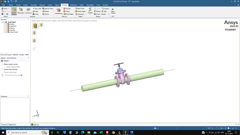
- After opening SpaceClaim in Fluent, import Geometry named as “Gate Valve. STEP”.
We can see the simplified geometry of Gate Valve as given below as well as the Structure of all parts mentioned as given below:
Simplified Geometry:
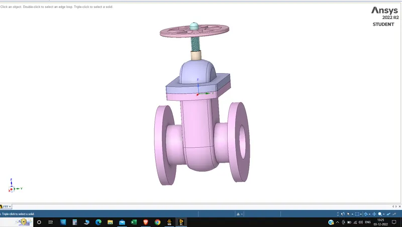
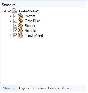
We can see all the parts listed in the Structure Tree.
After importing Geometry, hide the “Bottom” Part, so we can clearly see the “Gate Disc”.
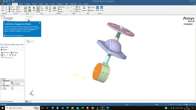
- Then Select “Gate Disc” component and move it upward direction by “10 mm” lift.
- To analyze the flow and its effects, we must allow the flow, and for that we have given “10 mm” lift to the “Gate Disc”.
- After lifting the “Gate Disc”, move the both face at inlet and outlet of the “Bottom” part by amount of 800 mm just to see the fluid flow and its effects as given below:
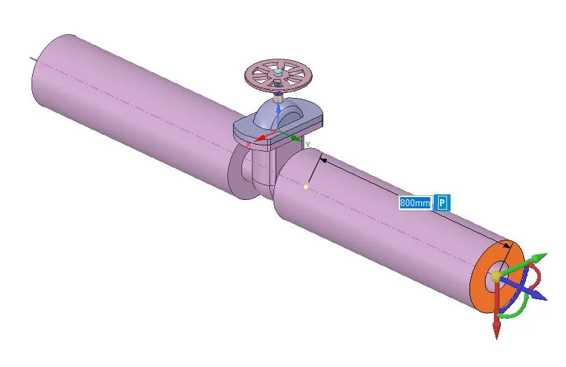
- After extension, create Fluid volume by selecting inlet, outlet and upper edges of the “Bottom” part.
Mesh:
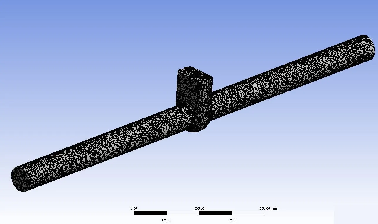
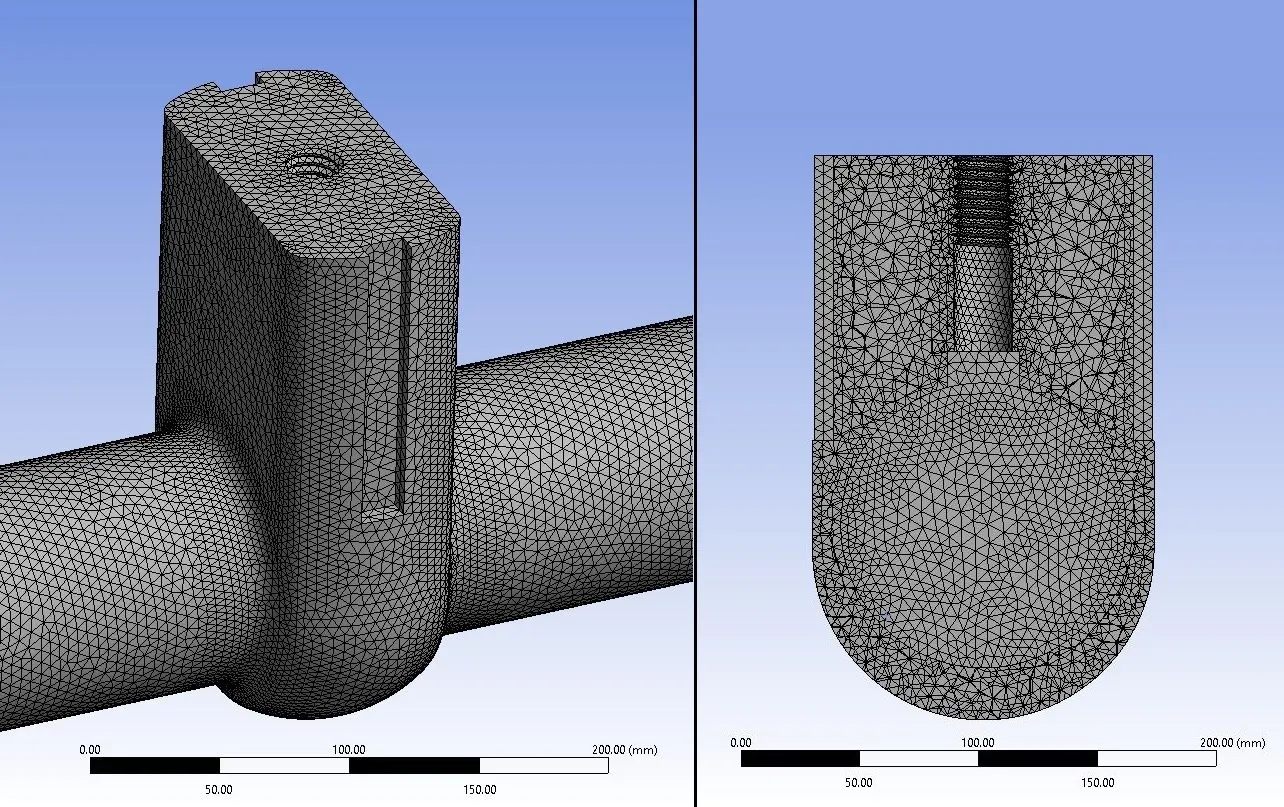
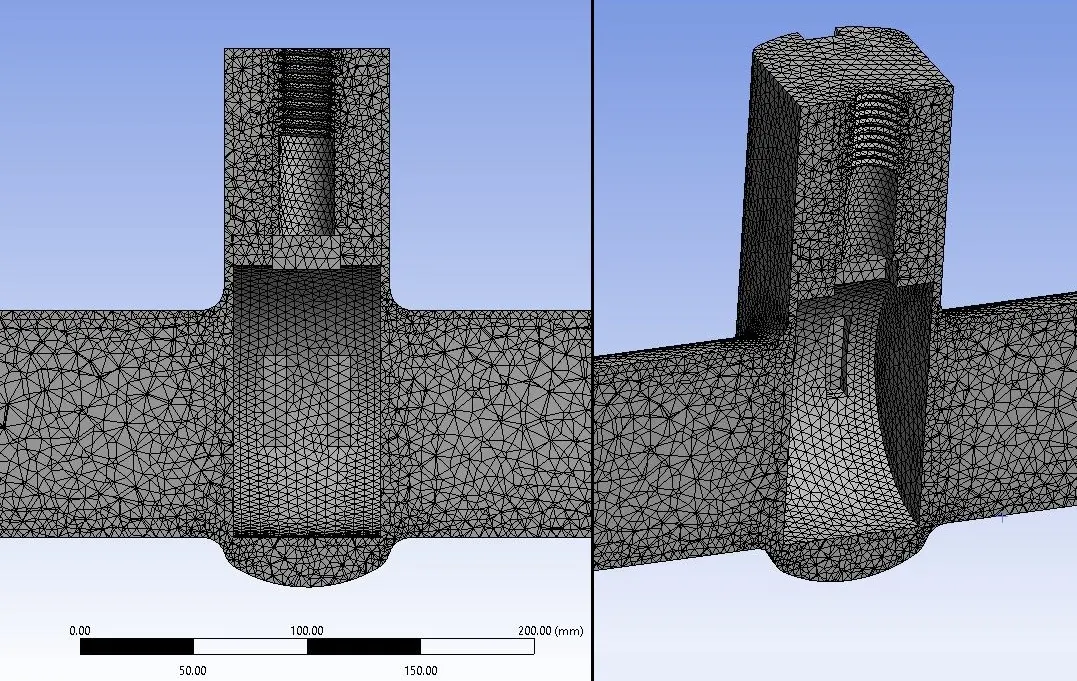
Mesh for the Fluid Volume of Gate valve, detailed as given below:
Details:
- Element Size: 5 mm
- of Elements: 597178
- of Nodes: 119029
- After Meshing, update it for further process and go for the Fluent Setup.
Model setup:
- Solver type: Pressure based
- Time steady : Steady
- Enable gravity with - 9.81 m/s2 on required axis
- Turbulence model: K epsillon > Realizable > Scaled wall function
- Fluid material : Water
- Cell zone : volume-volume > fluid > water
Boundary conditions:
- Inlet> pressure inlet = Gauge total pressure 10 Pascal
- Outlet>pressure outlet = Gauge total pressure 0 Pascal
Initialization : Hybrid
Run iterations = 300
Residual plots:
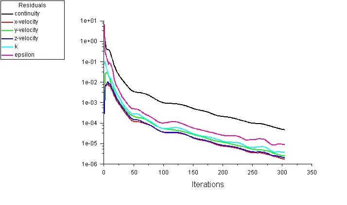
Case 1 : Lift 10 mm
Mass flow and Pressure outlet:
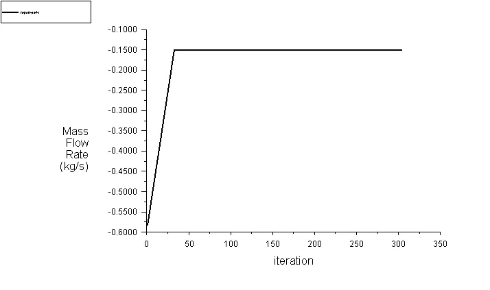
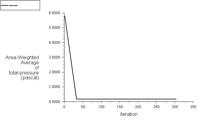
The value of mass flow obtained is 0.1838 kg/s and pressure outlet is 0.14928 Pa.
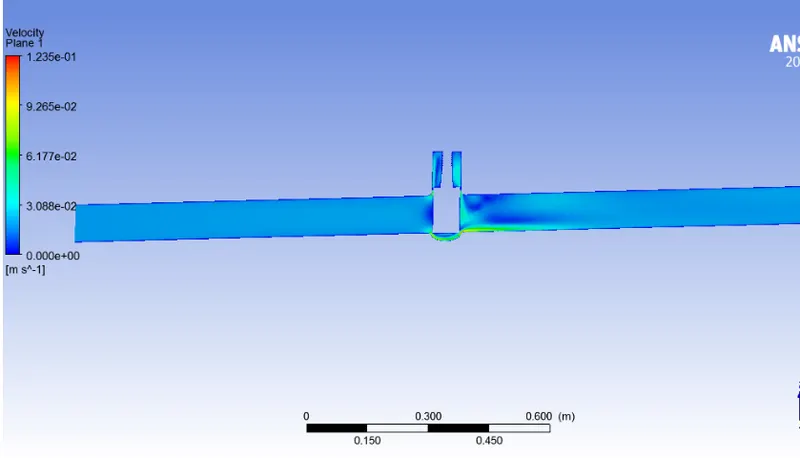
Velocity:
Case 2 : Lift 20 mm
Mass flow and Pressure outlet:
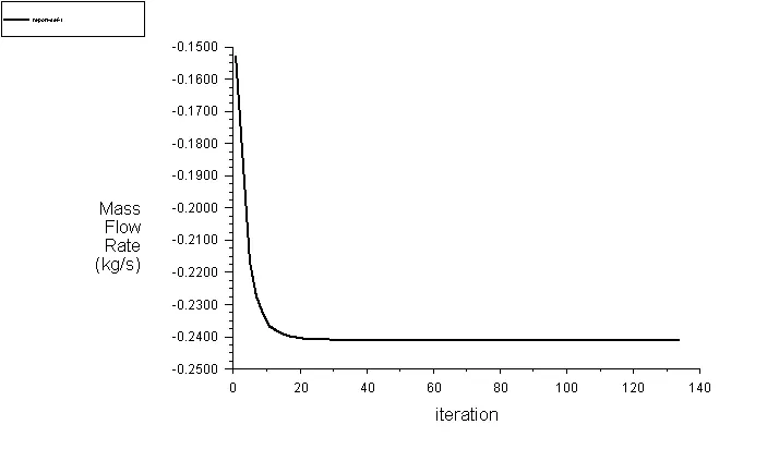
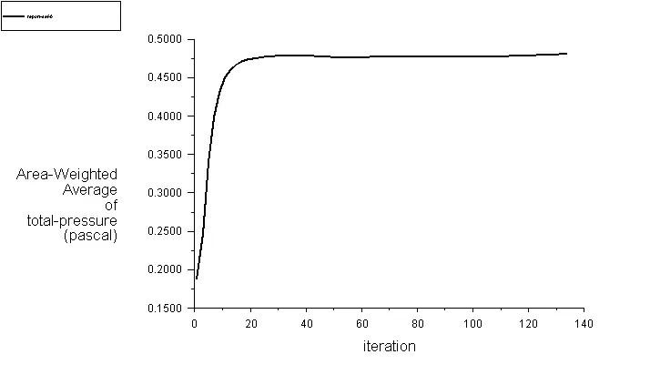
The value of mass flow obtained is 0.48132 kg/s and pressure outlet is 0.24069 Pa
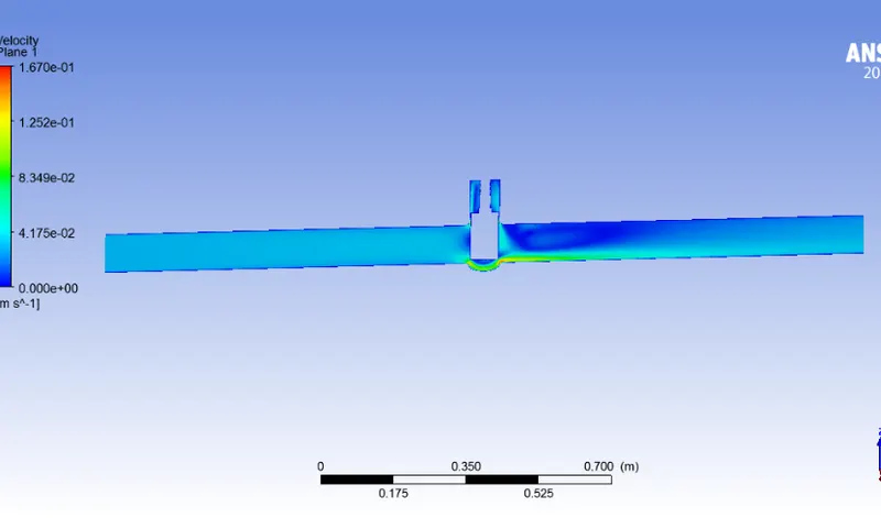
Velocity:
Case 3 : Lift 30 mm
Mass flow and Pressure outlet:
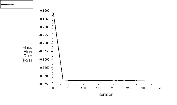
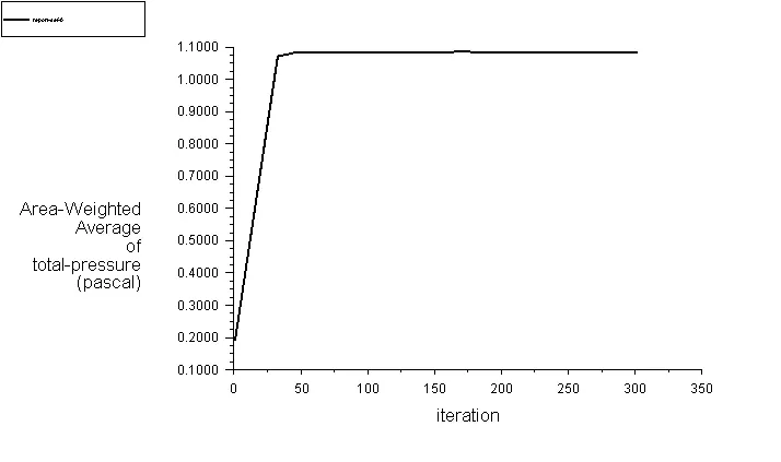
The value of mass flow obtained is 1.0853 kg/s and pressure outlet is 0.36311 Pa.
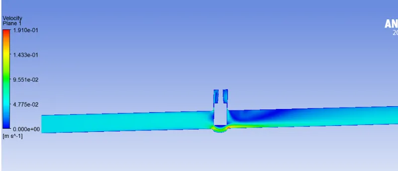
Velocity:
Case 4 : Lift 40 mm
Mass flow and Pressure outlet:
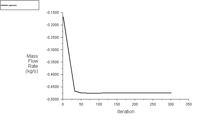
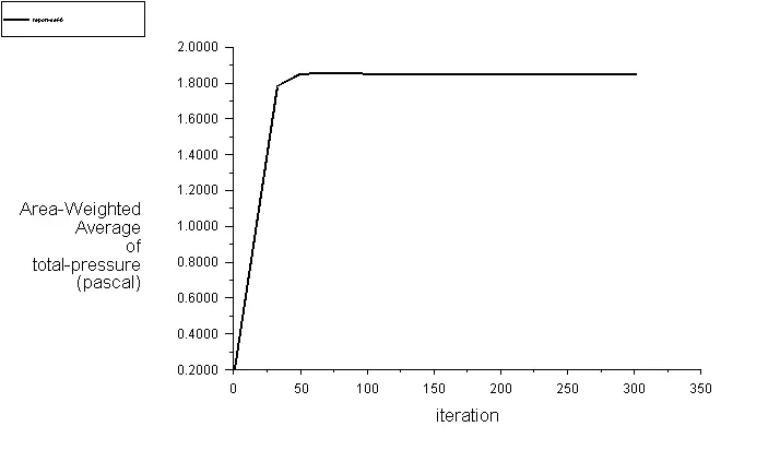
The value of mass flow obtained is 1.8533 kg/s and pressure outlet is 0.47429 Pa.
Velocity:
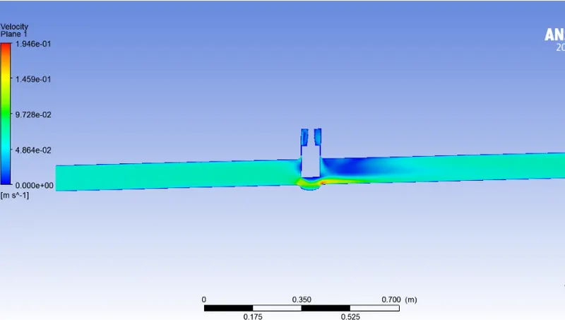
Case 5 : Lift 50 mm
Mass flow and Pressure outlet:
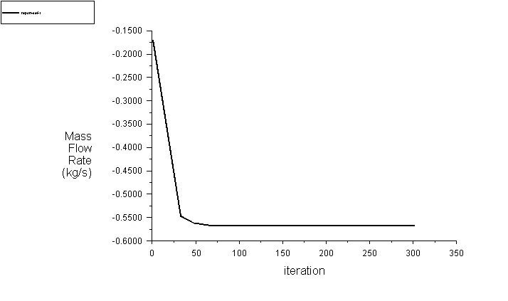
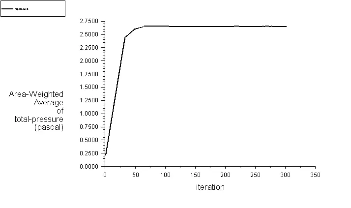
The value of mass flow obtained is 2.6583 kg/s and pressure outlet is 0.56672 Pa.
Velocity:
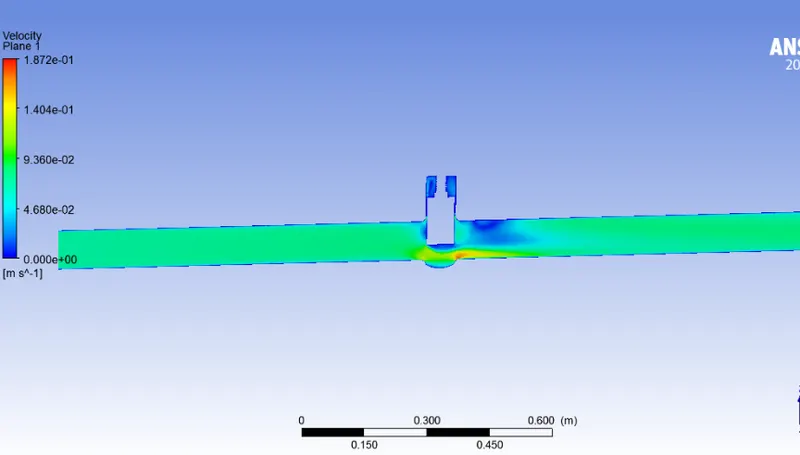
Case 6 : Lift 60 mm
Mass flow and Pressure outlet:
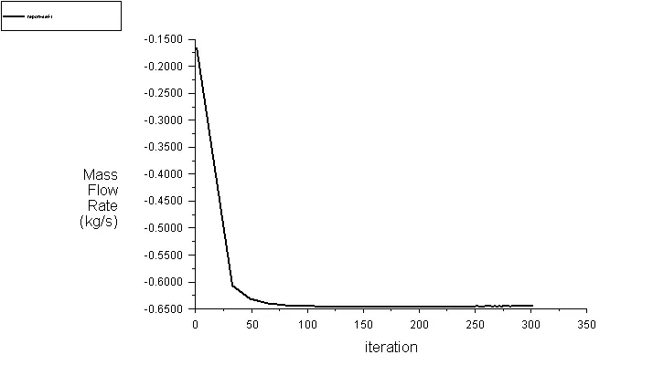
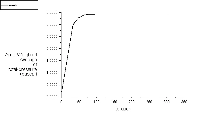
The value of mass flow obtained is 3.4323 kg/s and pressure outlet is 0.64389 Pa.
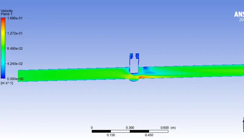
Velocity:
Case 7 : Lift 80 mm
Mass flow and Pressure outlet:
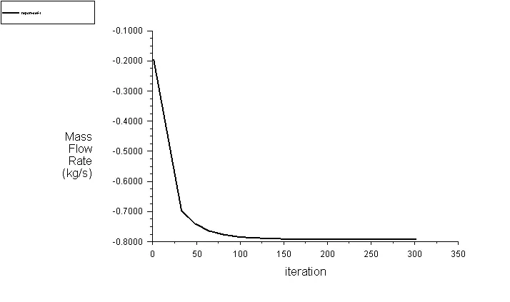
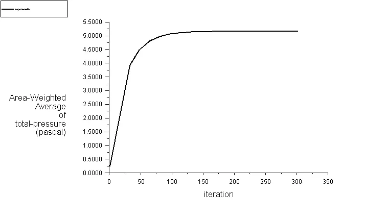
The value of mass flow obtained is 5.1798 kg/s and pressure outlet is 0.79033 Pa.
Velocity:
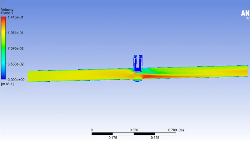
Flow coefficient (Cv):
The flow coefficient of a device is a relative measure of its efficiency at allowing fluid flow. It describes the relationship between the pressure drop across an orifies valve or other assembly and the corresponding flow rate.
Mathematically the flow coefficient Cv (or flow-capacity rating of the valve) can be expressed as :
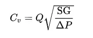
where:
- Q is the rate of flow (expressed in US gallons per minute),
- SG is the specific gravity of the fluid (for water = 1),
- ΔP is the pressure drop across the valve (expressed in psi).
Flow factor (Kv)
When selecting the correct valve type and size, various operands can be decisive. For example, the Kv factor, the flow rate and the characteristic value for the pressure drop help you to choose the right valve for the desired requirements and applications.
What does the flow factor Kv indicate?
The Kv factor is a standardised key figure for the achievable flow rate of a fluid through a valve and has been in use since the 1950s. The Kv factor is calculated according to standard DIN EN 60 534, wherein the value is defined according to VDE/VDI 2173 guidelines by the measurement of water at a pressure drop of approx. 1 bar and a temperature of 5-30°C. The unit of the result is given in m3/h.
In addition, this characteristic value of the valve only represents a certain valve stroke, i.e. a specific degree of opening. A valve has as many Kv factors as it has setting levels. An on/off valve therefore only has one Kv factor while control valves have Kv factors for each position. The key figure for the maximum 100% stroke is the Kvs factor.
Conclusion:
- We can conclude from observations that velocity in the first case is very low. As opening or lift of the Gate Disc increases, velocity of the flow increases.
- We can observe that at the front or inlet side of the valve, pressure is high. As flow passes through the valve opening, it decreases.
- At the outlet there are no any restrictions to the flow, so pressure becomes 0.
- It means there is minimum Pressure Drop.
- When the valve if fully open, Mass Flow rate and Flow Coefficient and Flow Factor becomes maximum.
- Thus, parametric study helps to analyze the different positions of valve opening and gives the benefit to get easily and quick results.