Week 9 - Parametric study on Gate valve.
Aim – parametric study on Gate valve using ANSYS fluent.
Introduction - A gate valve is generally used to completely shut off fluid flow or, in the fully open position, provide full flow in a pipeline. Thus it is used either in the fully closed or fully open positions. A gate valve consists of a valve body, seat and disc, a spindle, gland, and a wheel for operating the valve. The seat and the gate together perform the function of shutting off the flow of fluid.
Gate valves work by inserting a rectangular gate or wedge into the path of a flowing fluid. They are operated by a threaded stem which connects the actuator (generally a hand wheel or motor) to the stem of the gate. If the valve has a rising stem its position can be seen just by looking at the position of the stem.
Gate valves are characterized by a “gate” that closes in a plane perpendicular to the flow of fluid. They are used primarily for on/off, They are suitable for most fluids including steam, water, oil, air, and gas. In addition to on/off service, gate valves can be used for regulating flow.
Gate valves are more commonly used in refineries and petrochemical plants where pressure remains relatively low, but temperature may be very high.
Procedure- the complete process of simulation starting from space claim to result generation is shown below in the following steps.
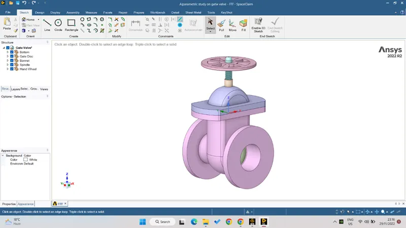
Step_1 – setting up the geometry in the space-claim.
- Open the step file geometry in the space claim as for the first step of the fluent.
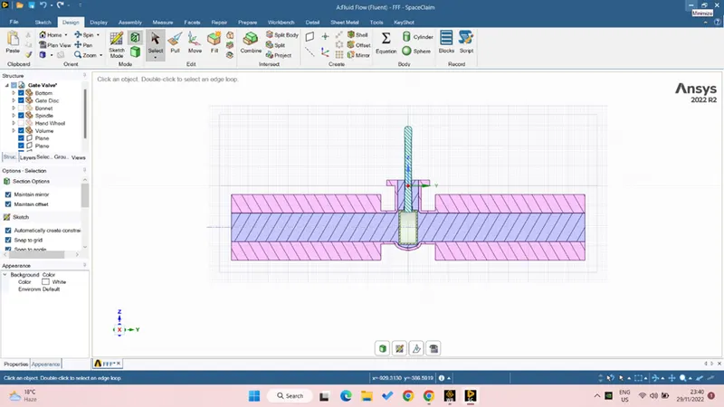
- Pull both side wall on the same direction for 500mm.
- Extract the fluid volume, while selecting the end edge which is adding the fluid volume to the outside wall.
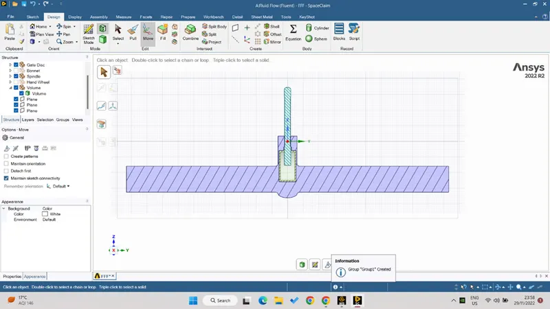
- Under move command select the gate geometry and move it for 1mm in the positive y direction.
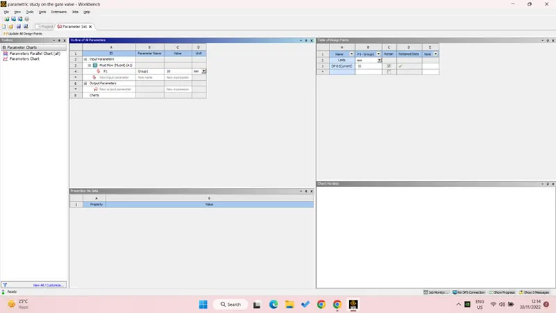
- From left side window select the create parameter> ruler diameter as 10mm now under volume< update volume body in the context.
- As the pipe diameter is given to 100mm we can create the parametric study range from 10-80mm by giving 10mm as the ruler distance.
- Now suppress the physics for bottom, gate, disc, bonate, spindle, hand wheel.
- Here the 6th step can be seen as the parametric study.
Step_2 – meshing and pre processing
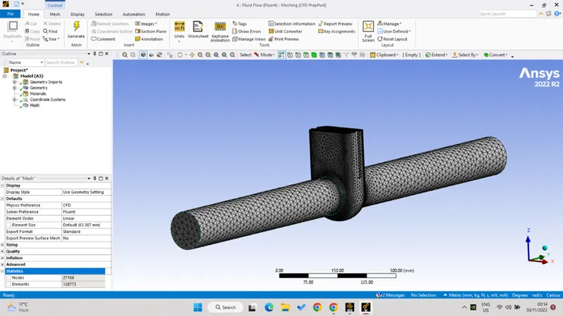
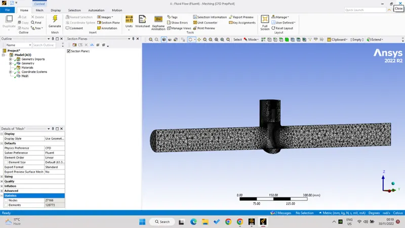
- Auto generate the CFD mesh, here the beauty of CFD mesh can be seen as the fine mesh is generated near the curve to see the changes because of the sudden change in the flued path.
- Also the plane geometry is having coarse mesh as there is no obstacle between the path.
- Name selection - one side is named as the inlet and the other side is named as the outlet for the fluid to flow.
- And the body is named as the water domain.
- Number of mesh element can be seen as the 1.2 lac.
- The cut section view of the model can also be seen in the second image which is showing the inside mesh, which is also the group of fine to cores mesh size for curve to plain geometry.
Step_3 solver and model setting.
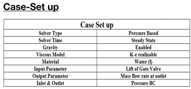
- The solver type is provided with the pressure based> absolute> steady state> gravity enabled> z direction -9.81m/s^2, as the general setting.
- The viscous model as the k-omega< RNG< swirl dominating flow.
- The method as coupled.
- Material as the water under fluid and delete the air ( but need to change the material from cell zone first ).
- Boundary condition inlet – pressure type< gauge pressure <10Pa (here we are not going to create the parametric group as the inlet pressure is going to be same for all the cases.
- Outlet pressure based < zero gauge pressure.
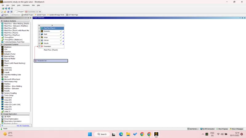
- Here under definition create the parameter to generate the [lot for the mass flow rate for under new surface< mass flow rate< print to console< enable create the parameter.
- Initialize the solution with the hybrid initialization.
Result – the following result has been obtained from the parametric simulation over the gate valve.
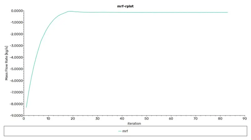
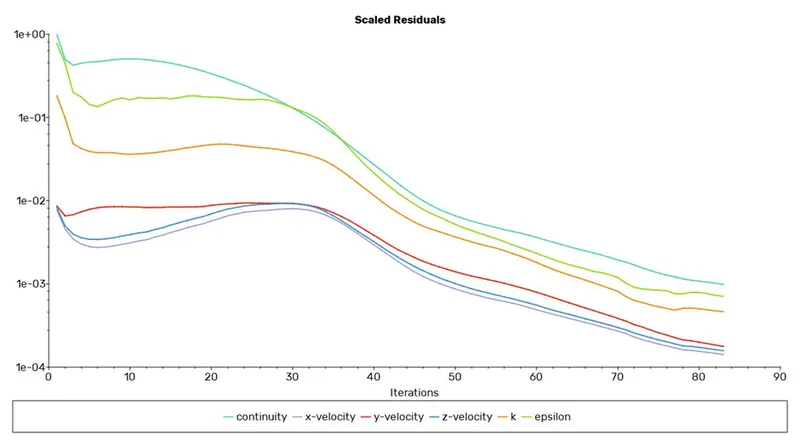
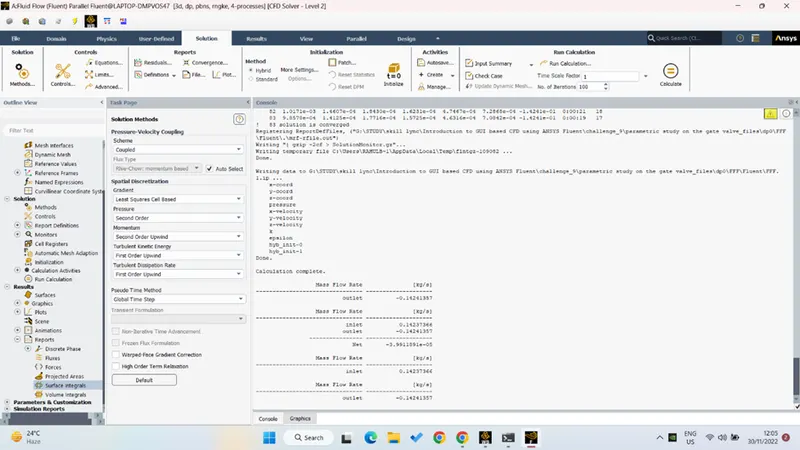
- Following presented plot is of mass flow rate and the residual of the equations, both plot is clearly showing the convergence has been achieved.
- the following contour is showing the velocity, its vector and the streamline for the 10 mm gate valve open.
- And the next three contour is showing the same plots for the last case of 80mm valve open.
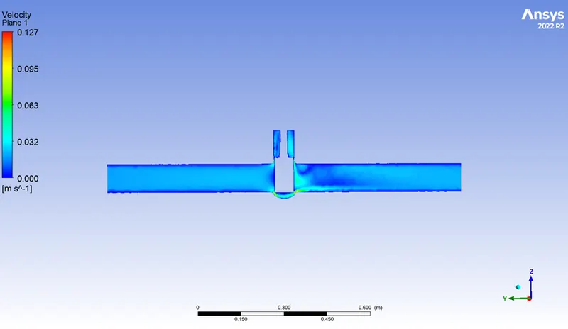
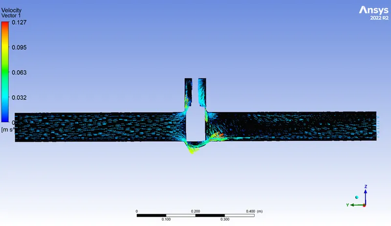
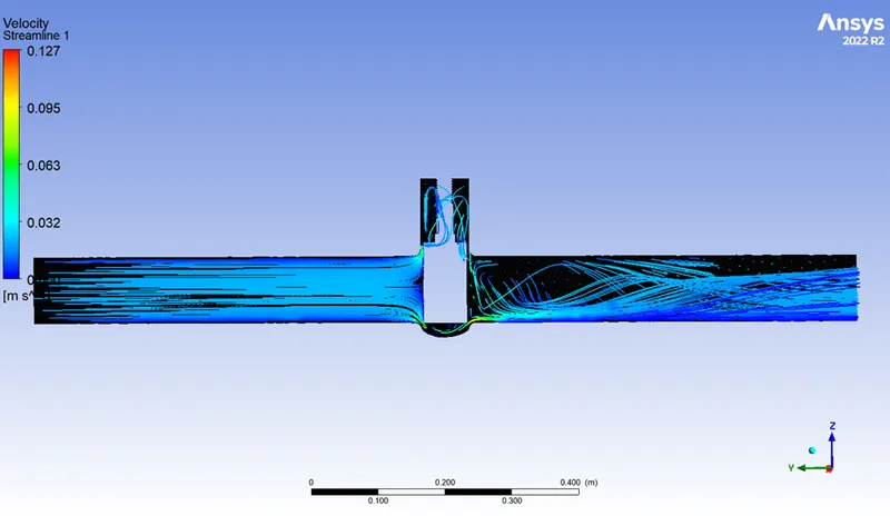
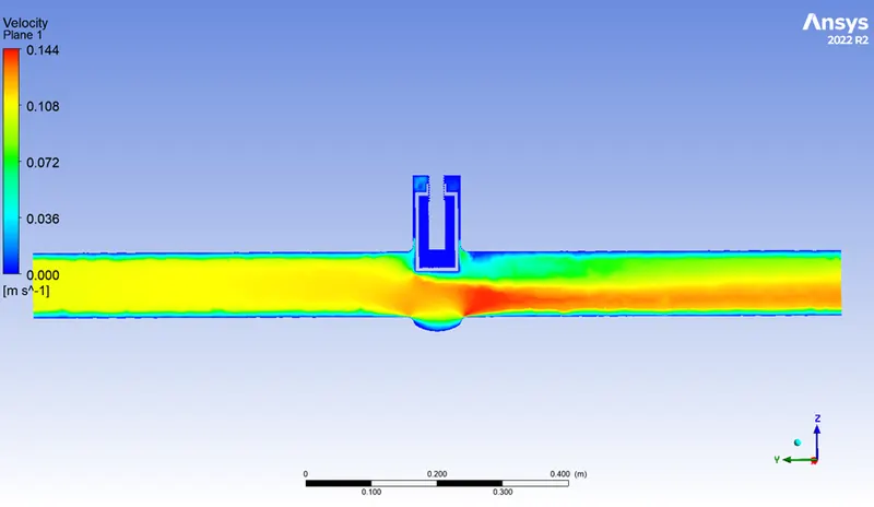
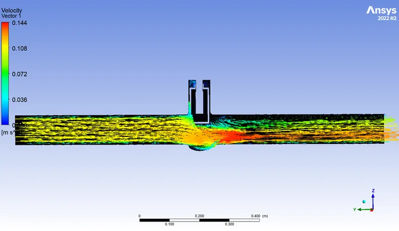
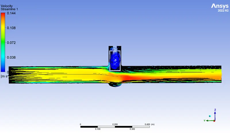
- Here the following conclusion can be obtained that as the cross section area is less( when the valve is just open in the first case) the velocity of the fluid is high at the particular region and as the gate gradually opening the velocity is decreasing.
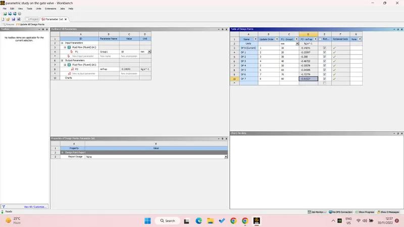
- Also mass flow rate is directionally proportional to the gate cross section area.
|
Case |
Ruler distance of gate (mm) |
Mass flow rate [kg s^-1] |
|
DP 0 |
10 |
-0.14241 |
|
DP 1 |
20 |
-0.23397 |
|
DP 2 |
30 |
-0.355 |
|
DP 3 |
40 |
-0.46722 |
|
DP 4 |
50 |
-0.55579 |
|
DP 5 |
60 |
-0.64389 |
|
DP 6 |
70 |
-0.72779 |
|
DP 7 |
80 |
-0.81527 |
- Here the negative sign is just the representation of that the mass is leaving the system.
- Also as the valve is being open gradually the mass flow rate is also increasing.
Learning outcome - When fully open, a gate valve has no obstruction in the flow path and so has a very low pressure drop. If the fluid is very viscous a special type of gate valve known as a knife gate valve can be used.
One reason that gate valves are not normally used to regulate flow is that the flow rate of the fluid is not proportional to the amount that the valve is open. Moreover, a partially open gate valve may suffer from vibration in which the valve may move from its assigned position. Also the gate and seat may be subject to excessive wear if the valve is partially open.
The gate valve is a block valve. Due to its design, it cannot control flow; even at the beginning of opening, erosion of the seat and disk occurs, resulting in the destruction of the tight faces.
Conclusion - Parametric study is a form of optimization where the user can run a series of analyses to investigate the impact of one or more processing parameter. For each parameter, any number of values can be selected for investigation. Each analysis is one possible combination of the parameter values chosen to be compared.
Here with the parametric study for the gate valve opening and further with this the calculation of mass flow rate also the animation of the particular case is the new learning.
In the fluent for any particular study of any model it is necessary to run the same model under different inlet boundary condition, doing this changes manually takes a lot of time thus parametric study helps in saving the time for such type of study.